AIRBAG SYSTEM, Diagnostic DTC:B1693/81

| DTC Code | DTC Name |
|---|---|
| B1693/81 | Driver Side Door Side Airbag Sensor Initialization Incomplete |
DESCRIPTION
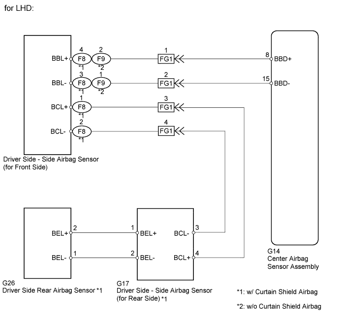
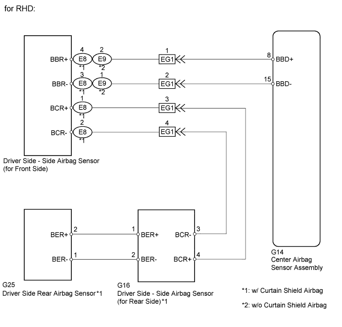
The circuit for the driver side - side collision sensor (to determine deployment of the front seat side airbag (driver side) and curtain shield airbag (driver side)*1) is composed of the center airbag sensor assembly, driver side - side airbag sensor (for front side) and driver side - side airbag sensor (for rear side)*1.
The driver side - side airbag sensor (for front side) and driver side - side airbag sensor (for rear side)*1 detect impacts to the vehicle and send signals to the center airbag sensor assembly to determine if the airbag should be deployed.
DTC B1693/81 is recorded when a malfunction is detected in the circuit for the driver side - side collision sensor (for front side) (to determine deployment of the front seat side airbag (driver side) and curtain shield airbag (driver side)*1).
| DTC No. | DTC Detection Condition | Trouble Area |
|---|---|---|
| B1693/81 | When one of following conditions is met:
|
|
*1: w/ Curtain Shield Airbag
WIRING DIAGRAM
INSPECTION PROCEDURE
PROCEDURE
-
CHECK PAST DTC
-
Turn the ignition switch to ON, and wait for at least 60 seconds.
-
Turn the ignition switch off.
-
Turn the ignition switch to ON, and wait for at least 60 seconds.
-
Check the past DTCs Click here.
Result Result Proceed to DTC B1692/81 is output A DTC B1697/82 is output B DTC B1692/81 and B1697/82 are not output C
A 
GO TO DTC B1692/81 Click here
B
GO TO DTC B1697/82 Click here
C 
-
-
CHECK CONNECTION OF CONNECTORS
-
Turn the ignition switch off.
-
Disconnect the negative (-) terminal cable from the battery, and wait for at least 90 seconds.
-
Check that the connectors are properly connected to the center airbag sensor assembly and driver side - side airbag sensor (for front side).
OK The connectors are properly connected.
NG
CONNECT CONNECTORS PROPERLY
OK
-
-
CHECK CONNECTORS
-
Disconnect the connectors from the center airbag sensor assembly and driver side - side airbag sensor (for front side).
-
Check that the connectors (on the center airbag sensor assembly side and driver side - side airbag sensor (for front side) side) are not damaged.
OK The connectors are not deformed or damaged.
NG
REPLACE HARNESS AND CONNECTOR
OK
-
-
SYSTEM CHECK
-
Check the vehicle specifications.
Result Result Proceed to w/ Curtain Shield Airbag A w/o Curtain Shield Airbag B
B 
CHECK DRIVER SIDE - SIDE AIRBAG SENSOR (FOR FRONT SIDE) CIRCUIT (CENTER AIRBAG SENSOR - SIDE AIRBAG SENSOR (FOR FRONT SIDE)) Click here
A
-
-
CHECK DRIVER SIDE - SIDE AIRBAG SENSOR (FOR FRONT SIDE) CIRCUIT (CENTER AIRBAG SENSOR - SIDE AIRBAG SENSOR (FOR FRONT SIDE))
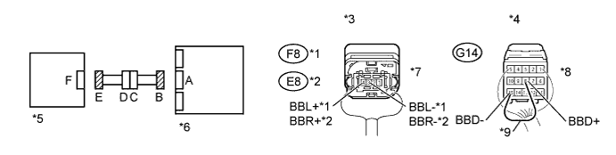
Text in Illustration *1 for LHD *6 Center Airbag Sensor Assembly *2 for RHD *7 Connector E *3 Rear view of wire harness connector
(to Driver Side - Side Airbag Sensor (for Front Side))
*8 Connector B *4 Rear view of wire harness connector
(to Center Airbag Sensor Assembly)
*9 Service Wire *5 Driver Side - Side Airbag Sensor (for Front Side) - -
-
Connect the negative (-) terminal cable to the battery, and wait for at least 2 seconds.
-
Turn the ignition switch to ON.
-
Measure the voltage according to the value(s) in the table below.
Standard Voltage for LHD Tester Connection Switch Condition Specified Condition F8-4 (BBL+) - Body ground Ignition switch ON Below 1 V F8-3 (BBL-) - Body ground Ignition switch ON Below 1 V for RHD Tester Connection Switch Condition Specified Condition E8-4 (BBR+) - Body ground Ignition switch ON Below 1 V E8-3 (BBR-) - Body ground Ignition switch ON Below 1 V -
Turn the ignition switch off.
-
Disconnect the negative (-) terminal cable from the battery, and wait for at least 90 seconds.
-
Using a service wire, connect terminals 8 (BBD+) and 15 (BBD-) of connector B.
Note
Do not forcibly insert a service wire into the terminals of the connector when connecting the wire.
-
Measure the resistance according to the value(s) in the table below.
Standard Resistance for LHD Tester Connection Condition Specified Condition F8-4 (BBL+) - F8-3 (BBL-) Always Below 1 Ω for RHD Tester Connection Condition Specified Condition E8-4 (BBR+) - E8-3 (BBR-) Always Below 1 Ω -
Disconnect the service wire from connector B.
-
Measure the resistance according to the value(s) in the table below.
Standard Resistance for LHD Tester Connection Condition Specified Condition F8-4 (BBL+) - F8-3 (BBL-) Always 1 MΩ or higher F8-4 (BBL+) - Body ground Always 1 MΩ or higher F8-3 (BBL-) - Body ground Always 1 MΩ or higher for RHD Tester Connection Condition Specified Condition E8-4 (BBR+) - E8-3 (BBR-) Always 1 MΩ or higher E8-4 (BBR+) - Body ground Always 1 MΩ or higher E8-3 (BBR-) - Body ground Always 1 MΩ or higher
NG
CHECK FLOOR WIRE (CENTER AIRBAG SENSOR - FRONT DOOR WIRE (DRIVER SIDE)) Click here
OK
-
-
CHECK DRIVER SIDE - SIDE AIRBAG SENSOR (FOR REAR SIDE) CIRCUIT
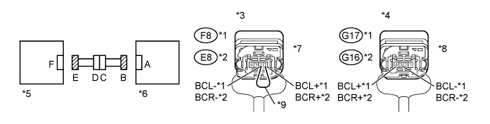
Text in Illustration *1 for LHD *6 Driver Side - Side Airbag Sensor (for Rear Side) *2 for RHD *7 Connector E *3 Rear view of wire harness connector
(to Driver Side - Side Airbag Sensor (for Front Side))
*8 Connector B *4 Rear view of wire harness connector
(to Driver Side - Side Airbag Sensor (for Rear Side))
*9 Service Wire *5 Driver Side - Side Airbag Sensor (for Front Side) - -
-
Disconnect the connectors from the driver side - side airbag sensor (for front side) and driver side - side airbag sensor (for rear side).
-
Connect the negative (-) terminal cable to the battery, and wait for at least 2 seconds.
-
Turn the ignition switch to ON.
-
Measure the voltage according to the value(s) in the table below.
Standard Voltage for LHD Tester Connection Switch Condition Specified Condition G17-4 (BCL+) - Body ground Ignition switch ON Below 1 V G17-3 (BCL-) - Body ground Ignition switch ON Below 1 V for RHD Tester Connection Switch Condition Specified Condition G16-4 (BCR+) - Body ground Ignition switch ON Below 1 V G16-3 (BCR-) - Body ground Ignition switch ON Below 1 V -
Turn the ignition switch off.
-
Disconnect the negative (-) terminal cable from the battery, and wait for at least 90 seconds.
-
Using a service wire, connect terminals 2 and 1 of connector E.
Note
Do not forcibly insert a service wire into the terminals of the connector when connecting the wire.
-
Measure the resistance according to the value(s) in the table below.
Standard Resistance for LHD Tester Connection Condition Specified Condition G17-4 (BCL+) - G17-3 (BCL-) Always Below 1 Ω for RHD Tester Connection Condition Specified Condition G16-4 (BCR+) - G16-3 (BCR-) Always Below 1 Ω -
Disconnect the service wire from connector E.
-
Measure the resistance according to the value(s) in the table below.
Standard Resistance for LHD Tester Connection Condition Specified Condition G17-4 (BCL+) - G17-3 (BCL-) Always 1 MΩ or higher G17-4 (BCL+) - Body ground Always 1 MΩ or higher G17-3 (BCL-) - Body ground Always 1 MΩ or higher for RHD Tester Connection Condition Specified Condition G16-4 (BCR+) - G16-3 (BCR-) Always 1 MΩ or higher G16-4 (BCR+) - Body ground Always 1 MΩ or higher G16-3 (BCR-) - Body ground Always 1 MΩ or higher
NG
CHECK FLOOR WIRE (SIDE AIRBAG SENSOR (FOR REAR SIDE) - FRONT DOOR WIRE) Click here
OK
-
-
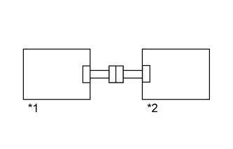
CHECK DRIVER SIDE - SIDE AIRBAG SENSOR (FOR FRONT SIDE)
Text in Illustration *1 Passenger Side - Side Airbag Sensor (for Front Side) *2 Center Airbag Sensor Assembly
-
Interchange the passenger side - side airbag sensor (for front side) with the driver side - side airbag sensor (for front side) and connect the connectors to them.
-
Connect the negative (-) terminal cable to the battery, and wait for at least 2 seconds.
-
Turn the ignition switch to ON, and wait for at least 60 seconds.
-
Clear the DTCs stored in the memory Click here.
-
Turn the ignition switch off.
-
Turn the ignition switch to ON, and wait for at least 90 seconds.
-
Check for DTCs Click here.
Result Result Proceed to DTC B1698/82 is output A DTC B1693/81 and B1698/82 are not output B DTC B1693/81 is output C
A
REPLACE DRIVER SIDE - SIDE AIRBAG SENSOR (FOR FRONT SIDE) Click here
B
USE SIMULATION METHOD TO CHECK Click here
C
-
-
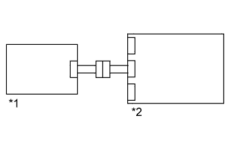
CHECK DRIVER SIDE - SIDE AIRBAG SENSOR (FOR REAR SIDE)
Text in Illustration *1 Passenger Side - Side Airbag Sensor (for Rear Side) *2 Driver Side - Side Airbag Sensor (for Front Side)
-
Interchange the passenger side - side airbag sensor (for rear side) with the driver side - side airbag sensor (for rear side) and connect the connectors to them.
-
Connect the negative (-) terminal cable to the battery, and wait for at least 2 seconds.
-
Turn the ignition switch to ON, and wait for at least 60 seconds.
-
Clear the DTCs stored in the memory Click here.
-
Turn the ignition switch off.
-
Turn the ignition switch to ON, and wait for at least 90 seconds.
-
Check for DTCs Click here.
Result Result Proceed to DTC B1693/81 is output A DTC B1698/82 is output B DTC B1693/81 and B1698/82 are not output C Tech Tips
DTCs other than B1693/81 and B1698/82 may be output at this time, but they are not related to this check.
A
REPLACE CENTER AIRBAG SENSOR ASSEMBLY Click here
B
REPLACE DRIVER SIDE - SIDE AIRBAG SENSOR (FOR REAR SIDE) Click here
C 
USE SIMULATION METHOD TO CHECK Click here
-
-
CHECK DRIVER SIDE - SIDE AIRBAG SENSOR (FOR FRONT SIDE) CIRCUIT (CENTER AIRBAG SENSOR - SIDE AIRBAG SENSOR (FOR FRONT SIDE))
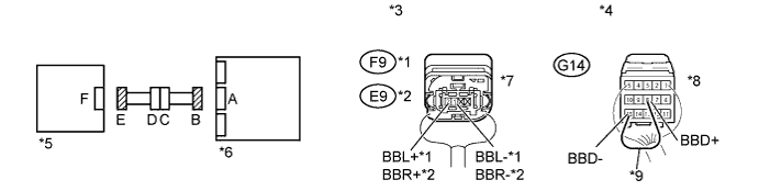
Text in Illustration *1 for LHD *6 Center Airbag Sensor Assembly *2 for RHD *7 Connector E *3 Rear view of wire harness connector
(to Driver Side - Side Airbag Sensor (for Front Side))
*8 Connector B *4 Rear view of wire harness connector
(to Center Airbag Sensor Assembly)
*9 Service Wire *5 Driver Side - Side Airbag Sensor (for Front Side) - -
-
Connect the negative (-) terminal cable to the battery, and wait for at least 2 seconds.
-
Turn the ignition switch to ON.
-
Measure the voltage according to the value(s) in the table below.
Standard Voltage for LHD Tester Connection Switch Condition Specified Condition F9-2 (BBL+) - Body ground Ignition switch ON Below 1 V F9-1 (BBL-) - Body ground Ignition switch ON Below 1 V for RHD Tester Connection Switch Condition Specified Condition E9-2 (BBR+) - Body ground Ignition switch ON Below 1 V E9-1 (BBR-) - Body ground Ignition switch ON Below 1 V -
Turn the ignition switch off.
-
Disconnect the negative (-) terminal cable from the battery, and wait for at least 90 seconds.
-
Using a service wire, connect terminals 8 (BBD+) and 15 (BBD-) of connector B.
Note
Do not forcibly insert a service wire into the terminals of the connector when connecting the wire.
-
Measure the resistance according to the value(s) in the table below.
Standard Resistance for LHD Tester Connection Condition Specified Condition F9-2 (BBL+) - F9-1 (BBL-) Always Below 1 Ω for RHD Tester Connection Condition Specified Condition E9-2 (BBR+) - E9-1 (BBR-) Always Below 1 Ω -
Disconnect the service wire from connector B.
-
Measure the resistance according to the value(s) in the table below.
Standard Resistance for LHD Tester Connection Condition Specified Condition F9-2 (BBL+) - F9-1 (BBL-) Always 1 MΩ or higher F9-2 (BBL+) - Body ground Always 1 MΩ or higher F9-1 (BBL-) - Body ground Always 1 MΩ or higher for RHD Tester Connection Condition Specified Condition E9-2 (BBR+) - E9-1 (BBR-) Always 1 MΩ or higher E9-2 (BBR+) - Body ground Always 1 MΩ or higher E9-1 (BBR-) - Body ground Always 1 MΩ or higher
NG
CHECK FLOOR WIRE (CENTER AIRBAG SENSOR - FRONT DOOR WIRE (DRIVER SIDE)) Click here
OK
-
-
CHECK DRIVER SIDE - SIDE AIRBAG SENSOR (FOR FRONT SIDE)
Text in Illustration *1 Passenger Side - Side Airbag Sensor (for Front Side) *2 Center Airbag Sensor Assembly
-
Interchange the passenger side - side airbag sensor (for front side) with the driver side - side airbag sensor (for front side) and connect the connectors to them.
-
Connect the negative (-) terminal cable to the battery, and wait for at least 2 seconds.
-
Turn the ignition switch to ON, and wait for at least 60 seconds.
-
Clear the DTCs stored in the memory Click here.
-
Turn the ignition switch off.
-
Turn the ignition switch to ON, and wait for at least 90 seconds.
-
Check for DTCs Click here.
Result Result Proceed to DTC B1698/82 is output A DTC B1693/81 and B1698/82 are not output B DTC B1693/81 is output C
A
REPLACE DRIVER SIDE - SIDE AIRBAG SENSOR (FOR FRONT SIDE) Click here
B
USE SIMULATION METHOD TO CHECK Click here
C
REPLACE CENTER AIRBAG SENSOR ASSEMBLY Click here
-
-
CHECK FLOOR WIRE (CENTER AIRBAG SENSOR - FRONT DOOR WIRE (DRIVER SIDE))
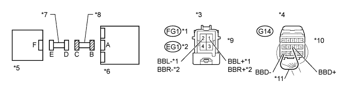
Text in Illustration *1 for LHD *7 Front Door Wire (Driver Side) *2 for RHD *8 Floor Wire *3 Front view of wire harness connector
(to Front Door Wire (Driver Side))
*9 Connector C *4 Rear view of wire harness connector
(to Center Airbag Sensor Assembly)
*10 Connector B *5 Driver Side - Side Airbag Sensor (for Front Side) *11 Service Wire *6 Center Airbag Sensor Assembly - -
-
Disconnect the floor wire connector from the front door wire (driver side).
-
Connect the negative (-) terminal cable to the battery, and wait for at least 2 seconds.
-
Turn the ignition switch to ON.
-
Measure the voltage according to the value(s) in the table below.
Standard Voltage for LHD Tester Connection Switch Condition Specified Condition FG1-1 (BBL+) - Body ground Ignition switch ON Below 1 V FG1-2 (BBL-) - Body ground Ignition switch ON Below 1 V for RHD Tester Connection Switch Condition Specified Condition EG1-1 (BBR+) - Body ground Ignition switch ON Below 1 V EG1-2 (BBR-) - Body ground Ignition switch ON Below 1 V -
Turn the ignition switch off.
-
Disconnect the negative (-) terminal cable from the battery, and wait for at least 90 seconds.
-
Using a service wire, connect terminals 8 (BBD+) and 15 (BBD-) of connector B.
Note
Do not forcibly insert a service wire into the terminals of the connector when connecting the wire.
-
Measure the resistance according to the value(s) in the table below.
Standard Resistance for LHD Tester Connection Condition Specified Condition FG1-1 (BBL+) - FG1-2 (BBL-) Always Below 1 Ω for RHD Tester Connection Condition Specified Condition EG1-1 (BBR+) - EG1-2 (BBR-) Always Below 1 Ω -
Disconnect the service wire from connector B.
-
Measure the resistance according to the value(s) in the table below.
Standard Resistance for LHD Tester Connection Condition Specified Condition FG1-1 (BBL+) - FG1-2 (BBL-) Always 1 MΩ or higher FG1-1 (BBL+) - Body ground Always 1 MΩ or higher FG1-2 (BBL-) - Body ground Always 1 MΩ or higher for RHD Tester Connection Condition Specified Condition EG1-1 (BBR+) - EG1-2 (BBR-) Always 1 MΩ or higher EG1-1 (BBR+) - Body ground Always 1 MΩ or higher EG1-2 (BBR-) - Body ground Always 1 MΩ or higher
NG
REPLACE FLOOR WIRE
OK
REPLACE FRONT DOOR WIRE (DRIVER SIDE)
-
-
CHECK FLOOR WIRE (SIDE AIRBAG SENSOR (FOR REAR SIDE) - FRONT DOOR WIRE)
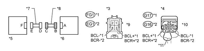
Text in Illustration *1 for LHD *7 Front Door Wire (Driver Side) *2 for RHD *8 Floor Wire *3 Front view of wire harness connector
(to Front Door Wire (Driver Side))
*9 Connector C *4 Rear view of wire harness connector
(to Driver Side - Side Airbag Sensor (for Rear Side))
*10 Connector B *5 Driver Side - Side Airbag Sensor (for Front Side) *11 Service Wire *6 Driver Side - Side Airbag Sensor (for Rear Side) - -
-
Disconnect the floor wire connector from the front door wire (driver side).
-
Connect the negative (-) terminal cable to the battery, and wait for at least 2 seconds.
-
Turn the ignition switch to ON.
-
Measure the voltage according to the value(s) in the table below.
Standard Voltage for LHD Tester Connection Switch Condition Specified Condition FG1-3 (BCL+) - Body ground Ignition switch ON Below 1 V FG1-4 (BCL-) - Body ground Ignition switch ON Below 1 V for RHD Tester Connection Switch Condition Specified Condition EG1-3 (BCR+) - Body ground Ignition switch ON Below 1 V EG1-4 (BCR-) - Body ground Ignition switch ON Below 1 V -
Turn the ignition switch off.
-
Disconnect the negative (-) terminal cable from the battery, and wait for at least 90 seconds.
-
Using a service wire, connect terminals 3 and 4 of connector B.
Note
Do not forcibly insert a service wire into the terminals of the connector when connecting the wire.
-
Measure the resistance according to the value(s) in the table below.
Standard Resistance for LHD Tester Connection Condition Specified Condition FG1-3 (BCL+) - FG1-4 (BCL-) Always Below 1 Ω for RHD Tester Connection Condition Specified Condition EG1-3 (BCR+) - EG1-4 (BCR-) Always Below 1 Ω -
Disconnect the service wire from connector B.
-
Measure the resistance according to the value(s) in the table below.
Standard Resistance for LHD Tester Connection Condition Specified Condition FG1-3 (BCL+) - FG1-4 (BCL-) Always 1 MΩ or higher FG1-3 (BCL+) - Body ground Always 1 MΩ or higher FG1-4 (BCL-) - Body ground Always 1 MΩ or higher for RHD Tester Connection Condition Specified Condition EG1-3 (BCR+) - EG1-4 (BCR-) Always 1 MΩ or higher EG1-3 (BCR+) - Body ground Always 1 MΩ or higher EG1-4 (BCR-) - Body ground Always 1 MΩ or higher
NG
REPLACE FLOOR WIRE
OK
REPLACE FRONT DOOR WIRE (DRIVER SIDE)
-