METER / GAUGE SYSTEM Fuel Gauge Malfunction
DESCRIPTION
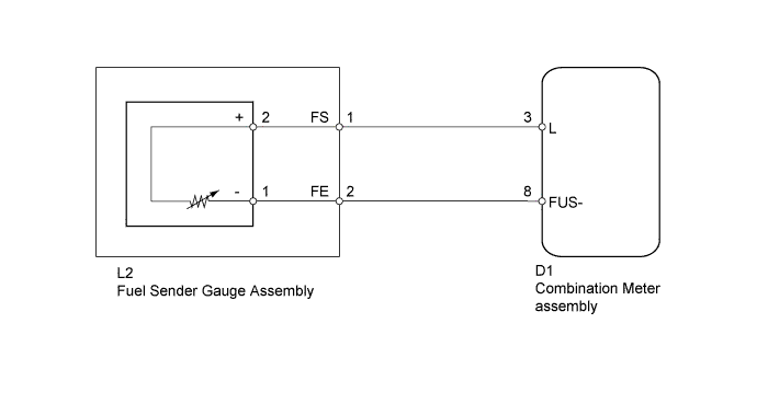
The combination meter assembly controls the fuel receiver gauge in accordance with the resistance of the fuel sender gauge, which varies depending on the amount of fuel remaining in the fuel tank.
WIRING DIAGRAM
INSPECTION PROCEDURE
PROCEDURE
-
CONFIRM DTC OUTPUT
-
Check DTC Click here.
Result Result Proceed to DTC B1500 is not output A DTC B1500 is output B
B 
GO TO DIAGNOSTIC TROUBLE CODE CHART Click here
A 
-
-
PERFORM ACTIVE TEST USING INTELLIGENT TESTER (FUEL METER)
-
Connect the intelligent tester to the DLC3.
-
Turn the ignition switch to ON.
-
Turn the tester on.
-
Enter the following menus: Body / Combination Meter / Active Test.
-
According to the display on the tester, perform the Active Test.
Combination Meter Tester Display Test part Control Range Diagnostic Note Fuel Meter Operation Fuel gauge EMPTY: Segment No. 1 flashes
1/2: Segments No. 1 to No. 3 illuminate
FULL: Segments No. 1 to No. 6 illuminate
-
NG
REPLACE COMBINATION METER ASSEMBLY Click here
OK
-
-
INSPECT FUEL SENDER GAGE ASSEMBLY
-
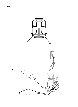
Text in Illustration *1 Component without harness connected
(Fuel Sender Gauge Assembly)
Remove the fuel sender gauge assembly.
-
Measure the resistance according to the value(s) in the table below.
Standard Resistance Tester Connection Condition Specified Condition 1 (-) - 2 (+) Float level is F (upper) 161 to 169 Ω Float level is E (lower) 405 to 415 Ω Result Result Proceed to OK A NG (for 1KR-FE) B NG (for 1NR-FE) C NG (for 1ND-TV) D -
Reinstall the fuel sender gauge assembly.
B
REPLACE FUEL SENDER GAUGE ASSEMBLY Click here
C
REPLACE FUEL SENDER GAUGE ASSEMBLY Click here
D
REPLACE FUEL SENDER GAUGE ASSEMBLY Click here
A
-
-
CHECK HARNESS AND CONNECTOR (COMBINATION METER ASSEMBLY - FUEL SENDER GAUGE ASSEMBLY)
-
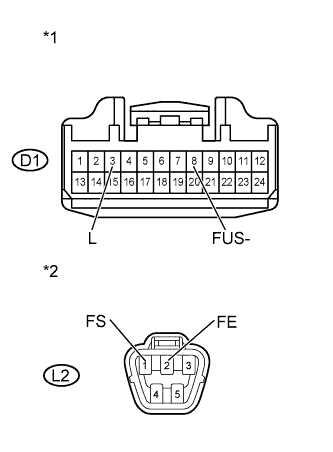
Text in Illustration *1 Front view of wire harness connector
(to Combination Meter Assembly)
*2 Front view of wire harness connector
(to Fuel Sender Gauge Assembly)
Disconnect the D1 combination meter assembly connector.
-
Disconnect the L2 fuel sender gauge assembly connector.
-
Measure the resistance according to the value(s) in the table below.
Standard Resistance Tester Connection Condition Specified Condition D1-3 (L) - L2-1 (FS) Always Below 1 Ω D1-3 (L) or L2-1 (FS) - Body ground Always 10 kΩ or higher D1-8 (FUS-) - L2-2 (FE) Always Below 1 Ω D1-8 (FUS-) or L2-2 (FE) - Body ground Always 10 kΩ or higher -
Reconnect the fuel sender gauge assembly connector.
-
Reconnect the combination meter assembly connector.
NG
REPAIR OR REPLACE HARNESS OR CONNECTOR
OK 
REPLACE COMBINATION METER ASSEMBLY Click here
-