METER / GAUGE SYSTEM Tachometer Malfunction
DESCRIPTION
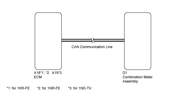
The combination meter assembly controls the tachometer in accordance with engine speed signals from the ECM through the CAN communication system.
WIRING DIAGRAM
INSPECTION PROCEDURE
PROCEDURE
-
CONFIRM DTC OUTPUT (CAN COMMUNICATION SYSTEM)
-
Check DTC Click here.
Result Result Proceed to DTC U0100 is not output A DTC U0100 is output B
B 
GO TO DIAGNOSTIC TROUBLE CODE CHART Click here
A 
-
-
CONFIRM DTC OUTPUT (ENGINE CONTROL SYSTEM)
-
Check DTC Click here.
Result Result Proceed to Engine control DTC is not output A Engine control DTC is output (for 1KR-FE) B Engine control DTC is output (for 1NR-FE) C Engine control DTC is output (for 1ND-TV) D
B
GO TO DIAGNOSTIC TROUBLE CODE CHART Click here
C
GO TO DIAGNOSTIC TROUBLE CODE CHART Click here
D
GO TO DIAGNOSTIC TROUBLE CODE CHART Click here
A
-
-
PERFORM ACTIVE TEST USING INTELLIGENT TESTER (TACHOMETER)
-
Connect the intelligent tester to the DLC3.
-
Turn the ignition switch to ON.
-
Turn the tester on.
-
Enter the following menus: Body / Combination Meter / Active Test.
-
According to the display on the tester, perform the Active Test.
Combination Meter Tester Display Test Part Control Range Diagnostic Note Tachometer Operation Tachometer 0/1000/2000/3000/4000/5000/ 6000/7000 rpm - OK Engine speed displayed on the tester is approximately the same as that of the tachometer reading.
NG
REPLACE COMBINATION METER ASSEMBLY Click here
OK
-
-
READ VALUE USING INTELLIGENT TESTER (TACHOMETER)
-
Connect the intelligent tester to the DLC3.
-
Start the engine.
-
Turn the tester on.
-
Enter the following menus: Body / Combination Meter / Data List.
-
According to the display on the tester, read the Data List.
Combination Meter Tester Display Measurement Item/Range Normal Condition Diagnostic Note Engine Rpm Engine speed
Min.: 0
Max.: 12750
Approximately same as actual engine speed (when engine is running) Unit: rpm OK Engine speed displayed on the tester is approximately the same as that displayed on the combination meter. Note
Determine whether the value displayed on the tester is within the acceptable range by referring to the reference values described in "On-Vehicle Inspection" Click here.
NG
REPLACE COMBINATION METER ASSEMBLY Click here
OK 
USE SIMULATION METHOD TO CHECK Click here
-