METER / GAUGE SYSTEM Speedometer Malfunction
DESCRIPTION
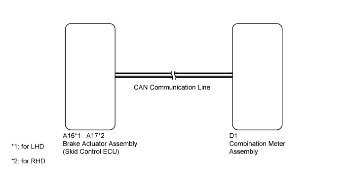
The combination meter assembly controls the speedometer in accordance with vehicle speed signals from the brake actuator through the CAN communication system.
WIRING DIAGRAM
INSPECTION PROCEDURE
PROCEDURE
-
CONFIRM DTC OUTPUT (CAN COMMUNICATION DTC)
-
Check DTC Click here.
Result Result Proceed to DTC U0129 is not output A DTC U0129 is output B
B 
GO TO DIAGNOSTIC TROUBLE CODE CHART Click here
A 
-
-
CONFIRM DTC OUTPUT (SPEED SENSOR DTC)
-
Check DTCs Click here.
Result Result Proceed to Vehicle stability control system is not output A Vehicle stability control system is output B
B
GO TO DIAGNOSTIC TROUBLE CODE CHART Click here
A
-
-
PERFORM ACTIVE TEST USING INTELLIGENT TESTER (SPEED METER)
-
Connect the intelligent tester to the DLC3.
-
Turn the ignition switch to ON.
-
Turn the tester on.
-
Enter the following menus: Body / Combination Meter / Active Test.
-
According to the display on the tester, perform the Active Test.
Combination Meter Tester Display Test Part Control Range Diagnostic Note Speed Meter Operation Speedometer 0 (0)/40 (24)/80 (48)/120 (72)/160 (96) km/h (mph) - OK Vehicle speed displayed on the tester is approximately the same as that of the speedometer reading.
NG
REPLACE COMBINATION METER ASSEMBLY Click here
OK
-
-
READ VALUE USING INTELLIGENT TESTER (VEHICLE SPEED METER)
-
Connect the intelligent tester to the DLC3.
-
Turn the ignition switch to ON.
-
Turn the tester on.
-
Enter the following menus: Body / Combination Meter / Data List.
-
According to the display on the tester, read the Data List.
Combination Meter Tester Display Measurement Item/Range Normal Condition Diagnostic Note Vehicle Speed Meter Vehicle speed /
Min.: 0 (0)
Max.: 255 (158)
Approximately same as actual vehicle speed (when vehicle is being driven) Unit km/h (mph) OK Vehicle speed displayed on the tester is approximately the same as the actual vehicle speed. Note
Determine whether the value displayed on the tester is within the acceptable range by referring to the reference values described in "On-Vehicle Inspection" Click here.
NG 
REPLACE COMBINATION METER ASSEMBLY Click here
OK 
USE SIMULATION METHOD TO CHECK Click here
-
-
REPLACE COMBINATION METER ASSEMBLY
-
Replace the combination meter assembly with a new or a normal one Click here.
OK The operation of the speedometer returns to normal.
NG
REPLACE BRAKE ACTUATOR ASSEMBLY Click here
OK
END
-