METER / GAUGE SYSTEM, Diagnostic DTC:B1500

| DTC Code | DTC Name |
|---|---|
| B1500 | Fuel Sender Open Detected |
DESCRIPTION
This DTC is stored when the combination meter assembly detects the fuel sender gauge assembly malfunction.
| DTC No. | DTC Detection Condition | Trouble Area |
|---|---|---|
| B1500 | When combination meter assembly detects fuel sender gauge assembly malfunction |
|
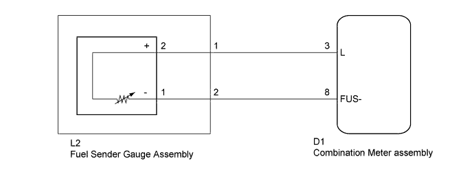
WIRING DIAGRAM
INSPECTION PROCEDURE
PROCEDURE
-
INSPECT FUEL SENDER GAUGE ASSEMBLY
-
Remove the fuel sender gauge assembly.
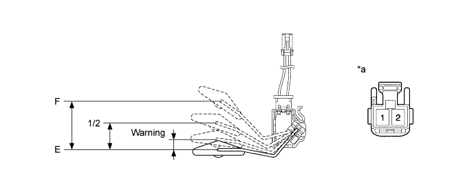
Text in Illustration *a Component without harness connected
(Fuel Sender Gauge Assembly)
- - -
Measure the resistance according to the value(s) in the table below.
Standard Resistance Tester Connection Float Level Float Position (mm (in.)) Specified Condition 1 (-) - 2 (+) F 42.5 to 57.7 (1.673 to 2.272) 161 to 178.5 Ω 1/2 27.6 to 34.7 (1.087 to 1.366) 277 Ω Warning 10.7 to 17.9 (0.421 to 0.705) 372 Ω E 0 386 to 415 Ω Result Result Proceed to OK A NG (for 1KR-FE) B NG (for 1NR-FE) C
B 
REPLACE FUEL SENDER GAUGE ASSEMBLY Click here
C
REPLACE FUEL SENDER GAUGE ASSEMBLY Click here
A 
-
-
CHECK HARNESS AND CONNECTOR (COMBINATION METER ASSEMBLY - FUEL SENDER GAUGE ASSEMBLY)
-
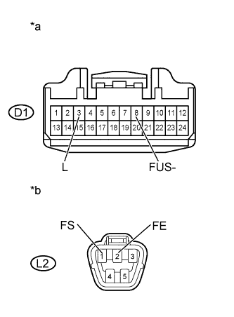
Text in Illustration *a Front view of wire harness connector
(to Combination Meter Assembly)
*b Front view of wire harness connector
(to Fuel Sender Gauge Assembly)
Disconnect the combination meter assembly connector.
-
Disconnect the fuel sender gauge assembly connector.
-
Measure the resistance according to the value(s) in the table below.
Standard Resistance Tester Connector Condition Specified Condition D1-3 (L) - L2-1 (FS) Always Below 1 Ω D1-3 (L) or L2-1 (FS) - Body ground Always 10 kΩ or higher D1-8 (FUS-) - L2-2 (FE) Always Below 1 Ω D1-8 (FUS-) or L2-2 (FE) - Body ground Always 10 kΩ or higher
NG
REPAIR OR REPLACE HARNESS OR CONNECTOR
OK 
REPLACE COMBINATION METER ASSEMBLY Click here
-