METER / GAUGE SYSTEM, Diagnostic DTC:B1500

| DTC Code | DTC Name |
|---|---|
| B1500 | Fuel Sender Open Detected |
DESCRIPTION
This DTC is stored when the combination meter detects the fuel sender gauge malfunction.
| DTC No. | DTC Detection Condition | Trouble Area |
|---|---|---|
| B1500 | When combination meter detects fuel sender gauge malfunction |
|
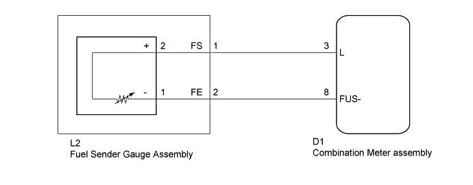
WIRING DIAGRAM
INSPECTION PROCEDURE
PROCEDURE
-
PERFORM ACTIVE TEST USING INTELLIGENT TESTER (FUEL METER)
-
Connect the intelligent tester to the DLC3.
-
Turn the ignition switch to ON.
-
Turn the intelligent tester on.
-
Enter the following menus: Body / Combination Meter / Active Test.
-
According to the display on the intelligent tester, perform the Active Test.
Combination Meter Item Test part Control Range Diagnostic Note Fuel Meter Operation Fuel gauge EMPTY: Segment No. 1 flashes
1/2: Segments No. 1 to No. 3 illuminate
FULL: Segments No. 1 to No. 6 illuminate
- OK Fuel receiver gauge segments are illuminated in accordance with the intelligent tester instructions.
NG 
REPLACE COMBINATION METER ASSEMBLY Click here
OK 
-
-
READ VALUE USING INTELLIGENT TESTER (FUEL INPUT)
-
Connect the intelligent tester to the DLC3.
-
Turn the ignition switch to ON.
-
Turn the intelligent tester on.
-
Enter the following menus: Body / Combination Meter / Data List.
-
According to the display on the intelligent tester, read the Data List.
Combination Meter Item Measurement Item/Range Normal Condition Diagnostic Note Fuel Input Fuel sender gauge input
Min.: 0
Max.: 127.5
Fuel sender input value Unit: Liter OK Fuel input signal displayed on the intelligent tester is approximately the same as the fuel receiver gauge indication.
NG 
INSPECT FUEL SENDER GAUGE ASSEMBLY Click here
OK 
REPLACE COMBINATION METER ASSEMBLY Click here
-
-
INSPECT FUEL SENDER GAUGE ASSEMBLY
-
Remove the fuel sender gauge assembly.
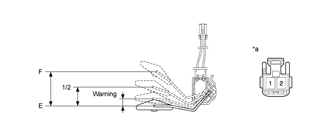
Text in Illustration *a Component without harness connected
(Fuel Sender Gauge Assembly)
- - -
Measure the resistance according to the value(s) in the table below.
Standard Resistance Tester Connection Float Level Float Position (mm (in.)) Specified Condition 1 (-) - 2 (+) F 42.5 to 57.7 (1.673 to 2.272) 161 to 178.5 Ω 1/2 27.6 to 34.7 (1.087 to 1.366) 277 Ω Warning 10.7 to 17.9 (0.421 to 0.705) 372 Ω E 0 386 to 415 Ω Result Result Proceed to OK A NG (for 1KR-FE) B NG (for 1NR-FE) C NG (for 1ND-TV) D -
Reinstall the fuel sender gauge assembly.
B
REPLACE FUEL SENDER GAUGE ASSEMBLY Click here
C
REPLACE FUEL SENDER GAUGE ASSEMBLY Click here
D
REPLACE FUEL SENDER GAUGE ASSEMBLY Click here
A
-
-
CHECK HARNESS AND CONNECTOR (COMBINATION METER ASSEMBLY - FUEL SENDER GAUGE ASSEMBLY)
-
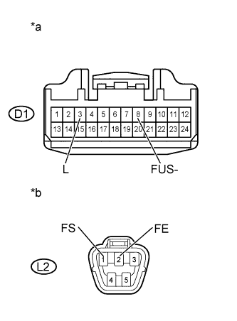
Text in Illustration *a Front view of wire harness connector
(to Combination Meter Assembly)
*b Front view of wire harness connector
(to Fuel Sender Gauge Assembly)
Disconnect the combination meter assembly connector.
-
Disconnect the fuel sender gauge assembly connector.
-
Measure the resistance according to the value(s) in the table below.
Standard Resistance Tester Connector Condition Specified Condition D1-3 (L) - L2-1 (FS) Always Below 1 Ω D1-3 (L) or L2-1 (FS) - Body ground Always 10 kΩ or higher D1-8 (FUS-) - L2-2 (FE) Always Below 1 Ω D1-8 (FUS-) or L2-2 (FE) - Body ground Always 10 kΩ or higher -
Reconnect the fuel sender gauge assembly connector.
-
Reconnect the combination meter assembly connector.
NG
REPAIR OR REPLACE HARNESS OR CONNECTOR
OK
REPLACE COMBINATION METER ASSEMBLY Click here
-