METER / GAUGE SYSTEM TERMINALS OF ECU

-
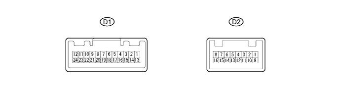
CHECK COMBINATION METER
-
Disconnect the D1 combination meter assembly connector.
-
Measure the voltage and resistance of the wire harness side connector.
Terminals No. (Symbol) Wiring Color Terminal Description Condition Specified Condition D1-1 (IG+) - Body ground SB - Body ground Ignition switch signal Ignition switch off → ON Below 1 V → 11 to 14 V D1-2 (B) - Body ground P - Body ground Battery Always 11 to 14 V D1-24 (ET) - Body ground BR - Body ground Ground Always Below 1 Ω If the result is not as specified, there may be a malfunction in the wire harness.
-
Reconnect the D1 combination meter assembly connector.
-
Measure the voltage of the wire harness side connector.
Terminals No. (Symbol) Wiring Color Terminal Description Condition Specified Condition D1-3 (L) - Body ground GR - Body ground Fuel level signal Ignition switch ON
Fuel level is FULL → EMPTY
Below 1 V → 4.5 to 9.0 V D1-4 (TX1-) - Body ground V- Body ground Ambient temperature sensor signal Ignition switch ON 4.5 to 5.5 V D1-5 (RRSB)*1 - Body ground LG - Body ground Rear seat inner belt assembly signal (RH side) Rear RH seat belt is unfastened → fastened Below 1 V → 11 to 14 V D1-6 (RLSB)*1 - Body ground R - Body ground Rear seat inner belt assembly signal (LH side) Rear LH seat belt is unfastened → fastened Below 1 V → 11 to 14 V D1-7 (RRBT)*1 - Body ground B - Body ground Rear RH seat belt warning light signal Rear RH seat belt warning light ON → OFF Below 1 V → 11 to 14 V D1-8 (FUS-) - Body ground BR - Body ground Fuel sender gauge ground Always Below 1 Ω D1-9 (RLBT)*1 - Body ground SB - Body ground Rear LH seat belt warning light signal Rear LH seat belt warning light ON → OFF Below 1 V → 11 to 14 V D1-10 (P/SB) - Body ground V - Body ground Front seat inner belt assembly signal (passenger side) Front passenger seat is occupied and its seat belt is unfastened → fastened Below 1 V → 11 to 14 V D1-11 (OILW)*2 - Body ground P - Body ground Oil level sensor signal Ignition switch ON 11 to 14V D1-12 (R)*3 - Body ground GR - Body ground M/T shift position signal (R) M/T shift warning buzzer OFF → ON Below 1 V → 11 to 14 V D1-14 (ILL+) - Body ground G - Body ground Taillight signal Light control switch OFF → ON Below 1 V → 11 to 14 V D1-15 (LP)*4 - Body ground SB - Body ground Security indicator light signal Security indicator light OFF → ON Below 1 V → 11 to 14 V D1-16 (+S) - Body ground BR - Body ground Speed signal (Output) Driving at approximately
20 km/h (12 mph)
Pulse generation
(See waveform 1)
D1-17 (SI) - Body ground G - Body ground Speed signal (Input) Driving at approximately
20 km/h (12 mph)
Pulse generation
(See waveform 1)
D1-20 (CANL) - Body ground W - Body ground CAN communication line Ignition switch ON Pulse generation D1-21 (CANH) - Body ground G - Body ground CAN communication line Ignition switch ON Pulse generation D1-23 (TX1+) - Body ground L - Body ground Ambient temperature sensor ground Always Below 1 Ω D2-1 (B) - Body ground P - Body ground Left turn signal Ignition switch ON
Left turn indicator light OFF → ON
Below 1 V → 11 to 14 V D2-2 (FOG)*5 - Body ground GR - Body ground Front fog signal Ignition switch ON
Front fog switch OFF → ON
Below 1 V → 11 to 14 V D2-3 (S) - Body ground W - Body ground Rear fog signal Ignition switch ON
Rear fog switch OFF → ON
Below 1 V → 11 to 14 V D2-5 (EFI) - Body ground BR - Body ground Check engine warning light signal Check engine warning light ON → OFF Below 1 V → 11 to 14 V D2-6 (S)*2 - Body ground SB - Body ground Fuel filter warning switch signal Fuel filter warning light ON → OFF Below 1 V → 11 to 14 V D2-7 (SW) - Body ground W - Body ground Brake fluid level warning light signal Ignition switch ON
Brake fluid level warning light ON → OFF
Below 1 V → 11 to 14 V D2-8 (CHG-) - Body ground R - Body ground Charge warning light signal Engine start
Charge warning light ON → OFF
Below 1 V → 11 to 14 V D2-9 (IND) - Body ground SB - Body ground Tail light indicator signal Light control switch ON → OFF Below 1 V → 11 to 14 V D2-10 (B) - Body ground L - Body ground Right turn signal Ignition switch ON
Right turn indicator light OFF → ON
Below 1 V → 11 to 14 V D2-11 (+) - Body ground B - Body ground High beam indicator signal (+) Always 11 to 14 V D2-13 (S) - Body ground LG - Body ground Engine oil pressure signal Engine oil pressure warning light ON → OFF Below 1 V → 11 to 14 V D2-14 (-) - Body ground W-B - Body ground High beam indicator signal (-) High beam indicator light ON → OFF Below 1 V → 11 to 14 V D2-16 (PBLT) - Body ground Y - Body ground Passenger seat belt warning light signal Ignition switch ON
Passenger seat belt warning light OFF → ON → OFF
Below 1 V → 11 to 14 V → Below 1 V
-
*1: w/ Rear seat belt warning system
-
*2: for 1ND-TV
-
*3: for Manual Transaxle
-
*4: w/ Theft Deterrent System
-
*5: w/ Front Fog Lights
If the result is not as specified, the combination meter assembly may have a malfunction.
-
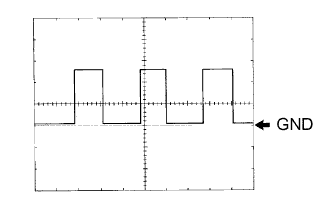
Waveform 1: Using an oscilloscope
Terminal Connections D1-16 (+S) and Body ground
D1-17 (SI) and Body ground
Tool Setting 5 V/DIV, 20 ms/DIV Condition Driving at approximately 20 km/h (12 mph) Tech Tips
As the vehicle speed increases, the cycle of the signal waveform narrows.
-
-
-
CHECK MAIN BODY ECU AND INSTRUMENT PANEL JUNCTION BLOCK
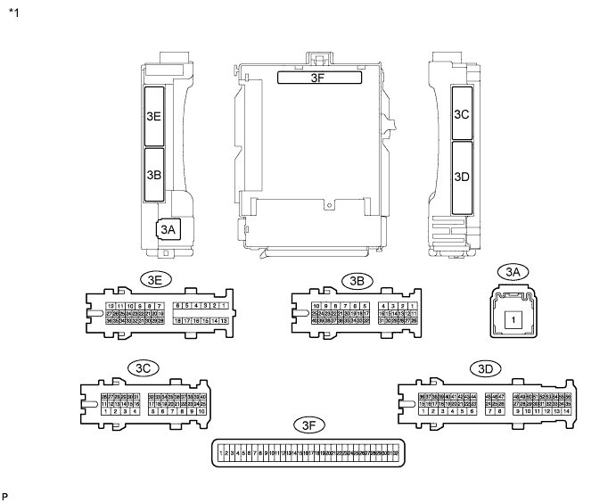
Text in Illustration *1 Instrument Panel Junction Block - - 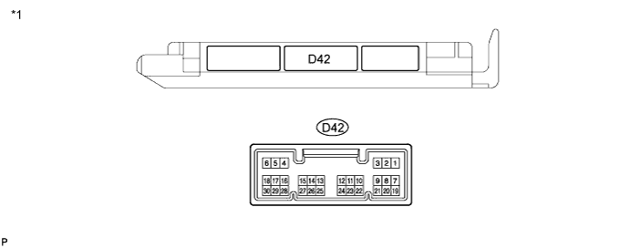
Text in Illustration *1 Main body ECU (w/ Theft Deterrent System) - - 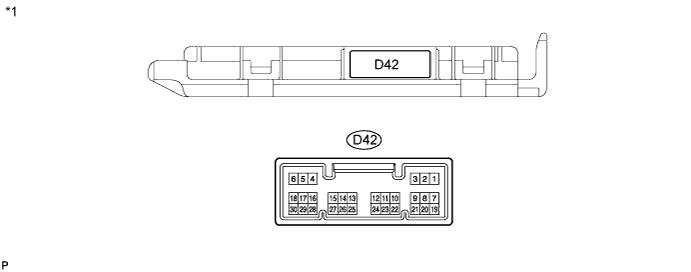
Text in Illustration *1 Main body ECU (w/o Theft Deterrent System) - -
-
Remove the main body ECU.
-
Disconnect the D42 main body ECU connector.
-
Measure the resistance and voltage between each terminal of the wire harness side connectors and body ground.
Terminal No. (Symbol) Wiring Color Terminal Description Condition Specified Condition 3F-11 (GND1) - Body ground - Ground Always Below 1 Ω 3F-29 (ACC)*1 - Body ground - Ignition power supply (ACC signal) Ignition switch ACC → off 11 to 14 V → Below 1 V 3F-30 (BECU) - Body ground - +B (power system signal system) power supply Always 11 to 14 V 3F-31 (ALTB) - Body ground - +B (power system alternator system) power supply Always 11 to 14 V 3F-32 (IG)*1 - Body ground - Ignition power supply (IG signal) Ignition switch ON → off 11 to 14 V → Below 1 V D42-19 (BCTY) - Body ground V - Body ground Back door courtesy switch input Back door CLOSED → OPEN 10 kΩ or higher → Below 1 Ω
-
*1: w/o Entry and Start System
If the result is not as specified, there may be a malfunction on the wire harness side.
-
-
Reinstall the main body ECU.
-
Reconnect the main body ECU connectors.
-
Measure the voltage between each terminal of the wire harness side connectors and body ground.
Terminal No. (Symbol) Wiring Color Terminal Description Condition Specified Condition 3C-33 (PKB) - Body ground R - Body ground Parking brake signal Parking brake warning light ON → OFF Below 1 V → 11 to 14 V 3E-20 (DBKL) - Body ground SB - Body ground Front seat inner belt assembly signal (driver side) Driver seat belt warning light OFF → ON Below 1 V → 11 to 14 V D42-13 (CANL) - Body ground W - Body ground CAN communication line Ignition switch ON Pulse generation D42-14 (CANH) - Body ground R - Body ground CAN communication line Ignition switch ON Pulse generation If the result is not as specified, there may be a malfunction in the wire harness.
-
-
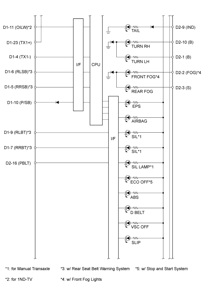
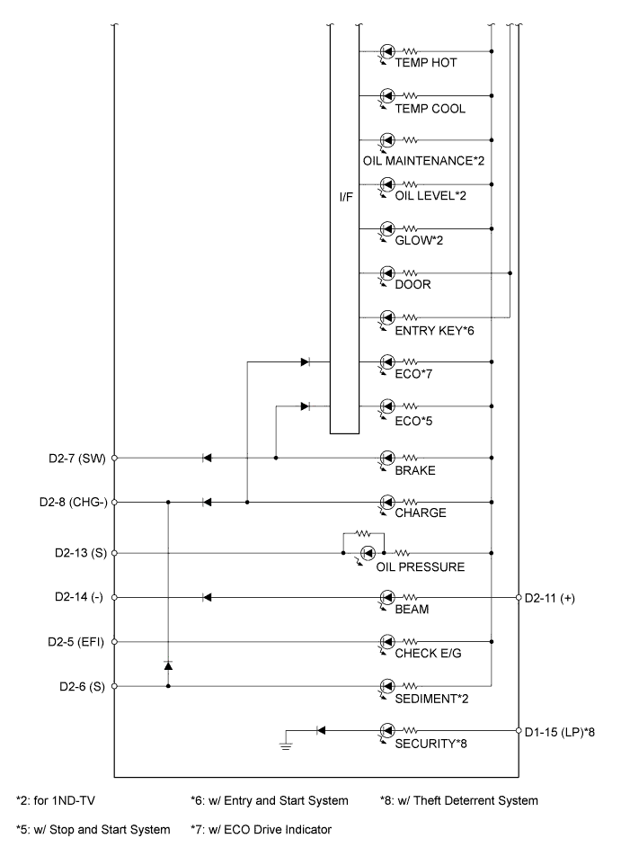
COMBINATION METER INTERNAL CIRCUIT
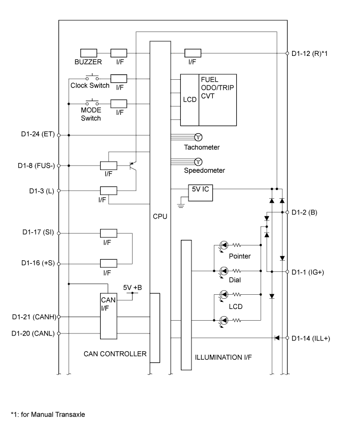
Connectors Terminal No. Wire Harness Side D1 1 IG2 relay*1
Backup boost converter*2
2 Battery 3 Fuel sender gauge assembly 4 Ambient temperature sensor 5 Rear seat inner belt assembly RH*3 6 Rear seat inner belt assembly RH*3 7 Telltale light assembly*3 8 Fuel sender gauge assembly 9 Telltale light assembly*3 10 Occupant detection sensor 11 Engine oil level sensor*4 12 Back-up light switch*5 14 Panel relay*6
Headlight dimmer switch*7
15 Main body ECU*8 16 Other ECU 17 Brake actuator assembly 20 CAN communication line 21 CAN communication line 23 Ambient temperature sensor 24 Body ground D2 1 Turn signal flasher assembly 2 FR FOG relay*9 3 RR FOG relay 5 ECM 6 Level warning switch*4 7 Brake fluid level warning switch 8 Generator 9 TAIL relay*6
Headlight dimmer switch*7
10 Turn signal flasher assembly 11 DIMMER relay*6
Battery*7
13 Engine oil pressure switch*1
Engine stop and start ECU*2
14 Body ground*6
Headlight dimmer switch*7
16 Telltale light assembly
-
*1: w/o Stop and Start System
-
*2: w/ Stop and Start System
-
*3: w/ Rear Seat Belt Warning System
-
*4: for 1ND-TV
-
*5: for Manual Transaxle
-
*6: w/ Daytime Running Light System or w/ Automatic Light Control System
-
*7: w/o Daytime Running Light System and w/o Automatic Light Control System
-
*8: w/ Theft Deterrent System
-
*9: w/ Front Fog Lights
-