AIRBAG SYSTEM PRECAUTION

CAUTION:
-
The vehicle is equipped with a Supplemental Restraint System (SRS), which consists of a steering pad, knee airbag, front passenger airbag, SRS seat cushion airbag, front seat side airbags, curtain shield airbags, rear window curtain shield airbag and front seat belt pretensioners. Failure to carry out service operations in the correct sequence could cause the SRS to unexpectedly deploy during servicing, possibly leading to a serious accident. Furthermore, if a mistake is made in servicing the SRS, it is possible that the SRS may fail to operate when required. Before performing servicing (including removal or installation of parts, inspection or replacement), be sure to read the following items carefully. Then follow the correct procedures as indicated in the repair manual.
-
Wait at least 90 seconds after the ignition switch is turned off and the negative (-) terminal cable is disconnected from the battery before starting the operation.
The SRS is equipped with a back-up power source, so if work is started within 90 seconds of disconnecting the negative (-) terminal cable of the battery, the SRS may be deployed.
-
Discharge static from your body before commencing repair work, to prevent an unexpected airbag deployment.
-
Do not directly expose the steering pad, knee airbag assembly, front passenger airbag assembly, SRS seat cushion airbag assembly, center airbag sensor assembly, front airbag sensor, front seat side airbag assembly, side airbag sensor (for front side), curtain shield airbag assembly, side airbag sensor (for rear side), rear window curtain shield airbag assembly, rear airbag sensor or front seat outer belt assembly to hot air or flames.
Note
-
Malfunction symptoms of the SRS are difficult to confirm, so DTCs are the most important source of information when troubleshooting. When troubleshooting the SRS, always inspect DTCs before disconnecting the battery.
-
Even in the case of a minor collision when the SRS does not deploy, the following parts should be inspected.
-
Steering pad
-
Knee airbag assembly
-
Front passenger airbag assembly
-
SRS seat cushion airbag assembly
-
Center airbag sensor assembly
-
Front airbag sensor
-
Front seat side airbag assembly
-
Side airbag sensor (for front side)
-
Curtain shield airbag assembly
-
Side airbag sensor (for rear side)
-
Rear window curtain shield airbag assembly
-
Rear airbag sensor
-
Front seat outer belt assembly
-
Before commencing repair work, remove the airbag sensor if any kind of shock is likely to occur to the airbag sensor during the operation.
-
Never use SRS parts from another vehicle. When replacing parts, replace them with new ones.
-
Never disassemble or repair any of the following parts in order to reuse them. If any of these parts have been dropped, or a defect is found (e.g. cracks, dents or any other defects) in any of the housings, brackets or connectors, then replace the part with a new one.
-
Steering pad
-
Knee airbag assembly
-
Front passenger airbag assembly
-
SRS seat cushion airbag assembly
-
Center airbag sensor assembly
-
Front airbag sensor
-
Front seat side airbag assembly
-
Side airbag sensor (for front side)
-
Curtain shield airbag assembly
-
Side airbag sensor (for rear side)
-
Rear window curtain shield airbag assembly
-
Rear airbag sensor
-
Front seat outer belt assembly
-
Use a volt/ohmmeter with high impedance (10 kΩ/V minimum) for troubleshooting the electrical circuits.
-
Information labels are attached to the periphery of the SRS components. Follow the instructions in the cautions.
-
After work on the SRS is completed, perform the SRS warning light check Click here.
-
When the negative (-) terminal cable is disconnected from the battery, the memory will be cleared. Therefore, make a record of the contents stored in each system before starting work. When the work is finished, reset each system as it was before. Never use a back-up power supply from outside the vehicle to avoid erasing the memory in any system.
-
If the vehicle is equipped with a mobile communication system, refer to the precautions in the Introduction section.
Tech Tips
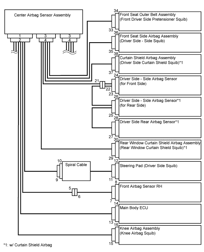
In the airbag system, the center airbag sensor assembly, front airbag sensor LH and RH, driver side - side airbag sensor and passenger side - side airbag sensor (for front side), driver side - side airbag sensor and passenger side - side airbag sensor (for rear side), and driver side rear airbag sensor and passenger side rear airbag sensor are collectively referred to as the airbag sensors.
-
HANDLING PRECAUTIONS FOR AIRBAG SENSORS
-
Before starting the following operations, wait for at least 90 seconds after disconnecting the negative (-) terminal cable from the battery:
-
Replacement of the airbag sensors
-
Adjustment of the front doors and back door of the vehicle equipped with the side airbags, curtain shield airbags and rear window curtain shield airbag (fitting adjustment)
-
-
When connecting or disconnecting the airbag sensor connectors, ensure that each sensor is installed in the vehicle.
-
Do not use the airbag sensors which have been dropped during the operation or transportation.
-
Do not disassemble the airbag sensors.
-
-
INSPECTION PROCEDURE FOR VEHICLE INVOLVED IN ACCIDENT
-
When the airbag has not deployed, confirm the DTCs by checking the SRS warning light. If there is any malfunction in the SRS airbag system, perform troubleshooting.
-
When any of the airbags have deployed, replace the airbag sensors and check the installation condition.
-
-
IGNITION SWITCH EXPRESSIONS
-
The type of ignition switch used on this model differs according to the specifications of the vehicle. The expressions listed in the table below are used in this section.
Expression Ignition Switch (Position) Engine Switch (Condition) Ignition switch off LOCK Off Ignition switch ACC ACC On (ACC) Ignition switch ON ON On (IG) Engine start START Start
-
-
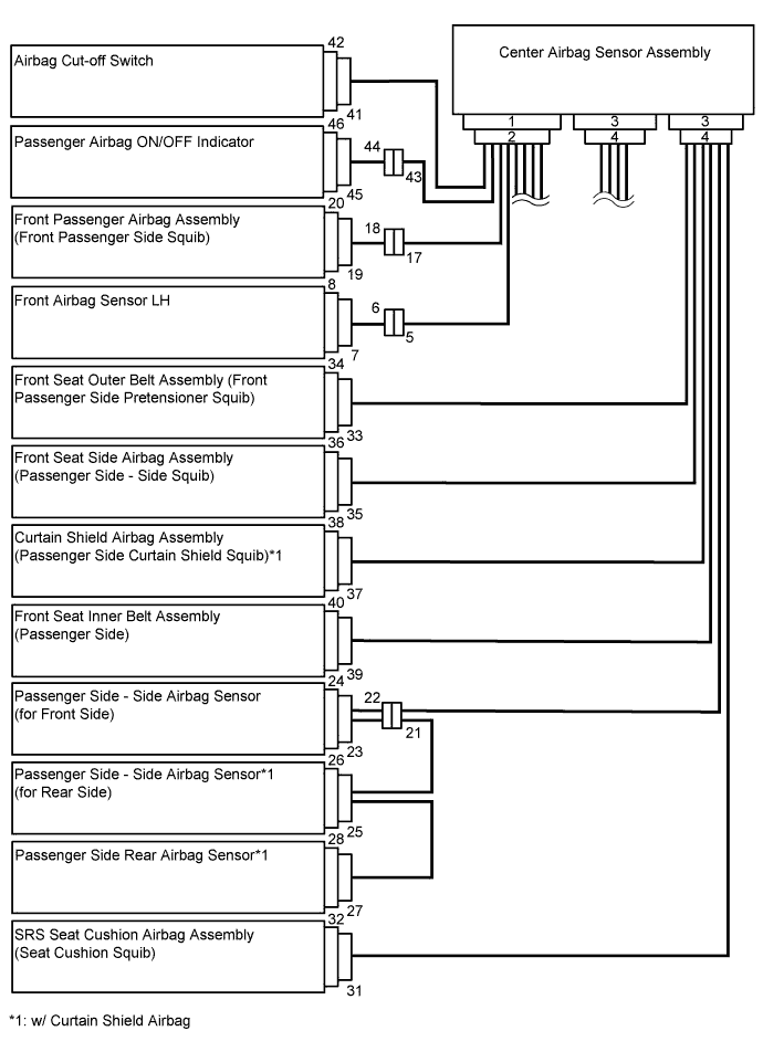
SRS CONNECTORS
-
SRS connectors are located as shown in the following illustration.
No. Item Application (1) Terminal Twin-Lock Mechanism Connectors 5, 6, 9, 10, 17, 18, 21, 22, 23, 25, 31, 35 (2) Activation Prevention Mechanism Connectors 2, 4, 10, 12, 16, 18, 20, 30, 32, 34, 36, 38 (3) Half Connection Prevention Mechanism Connectors 6, 9, 17, 18, 22, 31 (4) Connector Position Assurance Mechanism Connector 7, 23, 25, 27, 35 (5) Connector Lock Mechanism (1) Connectors 11, 15, 19, 29, 33, 37 (6) Connector Lock Mechanism (2) Connectors 2, 4 (7) Improper Connection Prevention Lock Mechanism Connectors 1, 3 -
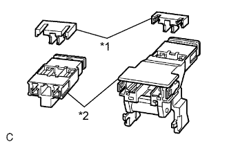
Text in Illustration *1 Spacer *2 Housing All connectors in the SRS are colored yellow to distinguish them from other connectors. Some connectors have special functions, and are specially designed for the SRS. These connectors use durable gold-plated terminals, and are placed in the locations shown above to ensure high reliability.
-
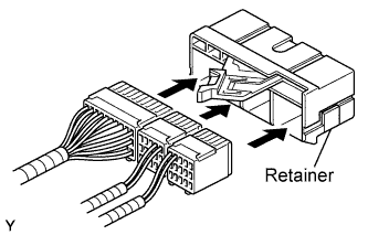
Terminal twin-lock mechanism:
Each connector is a two-piece component consisting of a housing and a spacer. This design enables the terminal to be locked securely by two locking devices (the retainer and the lance) to prevent the terminals from becoming disconnected.
-
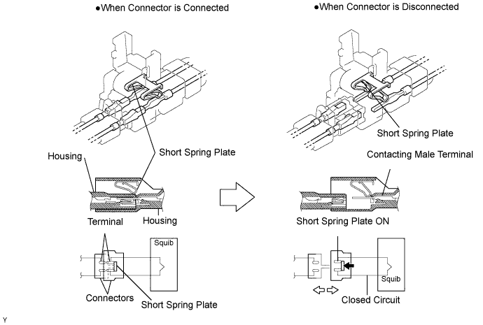
Activation prevention mechanism:
Each connector contains a short spring plate. When the connector is disconnected, the short spring plate creates a short circuit by automatically connecting the positive (+) and negative (-) terminals of the squib.
-
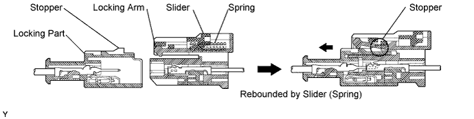
Half connection prevention mechanism:
If the connector is not completely connected, the connector is disconnected by the spring operation so that no continuity exists.
-
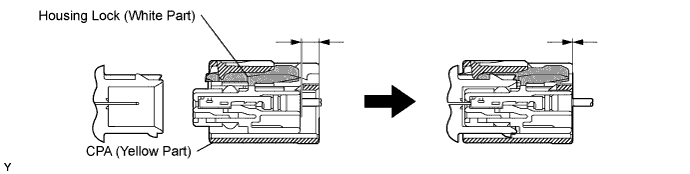
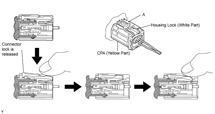
Connector position assurance mechanism:
The CPA (yellow part) slides, which completes the connector engagement, only when the housing lock (white part) is completely engaged.
-
Connector lock mechanism (1):
Locking the connector lock button connects the connector.

-
Connector lock mechanism (2):
Both the primary lock with holder lances and the secondary lock with a retainer prevent the connectors from becoming disconnected.
-
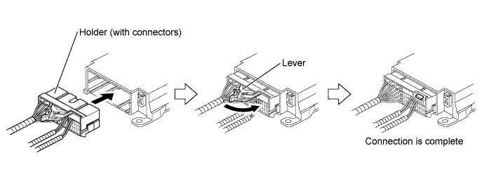
Improper connection prevention lock mechanism:
When connecting the holder, the lever is pushed into the end by rotating around the A axis to lock the holder securely.
-
-
-
DISCONNECTION OF CONNECTORS FOR STEERING PAD, FRONT PASSENGER AIRBAG ASSEMBLY (SQUIB SIDE), KNEE AIRBAG ASSEMBLY, CURTAIN SHIELD AIRBAG ASSEMBLY AND REAR WINDOW CURTAIN SHIELD AIRBAG ASSEMBLY
Tech Tips
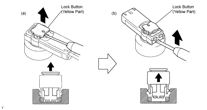
Tape the screwdriver tip before use.
-
Release the lock button (yellow part) of the connector using a screwdriver.
-
Insert the screwdriver tip between the connector and the base, and then raise the connector.
-
-
CONNECTION OF CONNECTORS FOR STEERING PAD, FRONT PASSENGER AIRBAG ASSEMBLY (SQUIB SIDE), KNEE AIRBAG ASSEMBLY, CURTAIN SHIELD AIRBAG ASSEMBLY AND REAR WINDOW CURTAIN SHIELD AIRBAG ASSEMBLY
-
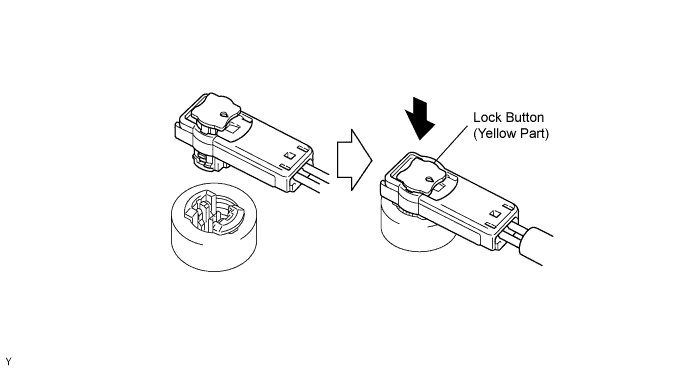
Connect the connector.
-
Push the lock button (yellow part) of the connector down securely. When locking, a click sound can be heard.
-
-
DISCONNECTION OF CONNECTORS FOR FRONT SEAT OUTER BELT ASSEMBLY
Tech Tips
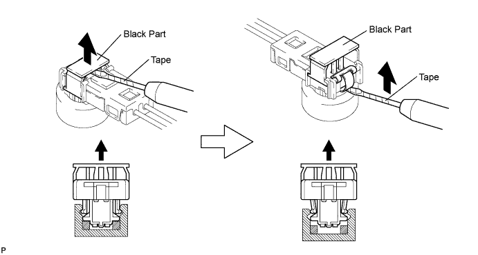
Tape the screwdriver tip before use.
-
Release the lock button (black part) of the connector using a screwdriver.
-
Insert the screwdriver tip between the connector and the base, and then raise the connector.
-
-
CONNECTION OF CONNECTORS FOR FRONT SEAT OUTER BELT ASSEMBLY
-
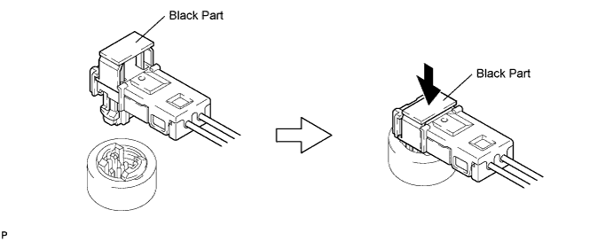
Connect the connector.
-
Push down securely on the lock button (black part) of the connector. When locking, a click sound can be heard
-
-
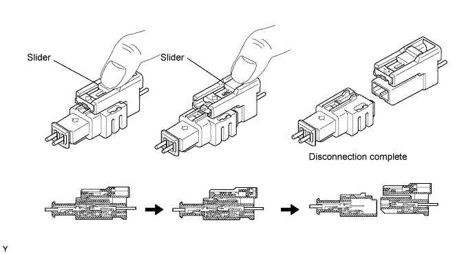
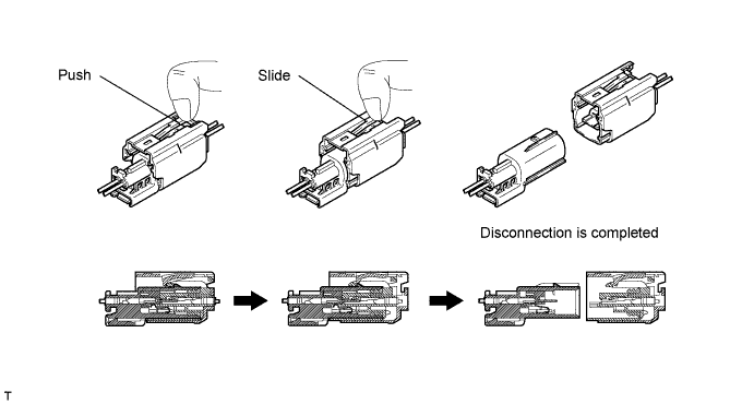
DISCONNECTION OF CONNECTORS FOR SPIRAL CABLE (INSTRUMENT PANEL WIRE SIDE), FRONT PASSENGER AIRBAG ASSEMBLY (INSTRUMENT PANEL WIRE SIDE) AND FRONT AIRBAG SENSOR (INSTRUMENT PANEL WIRE SIDE)
-
Place a finger on the slider, slide the slider to release the lock, and then disconnect the connector.
-
-
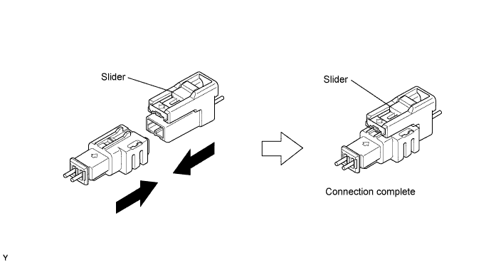
CONNECTION OF CONNECTORS FOR SPIRAL CABLE (INSTRUMENT PANEL WIRE SIDE), FRONT PASSENGER AIRBAG ASSEMBLY (INSTRUMENT PANEL WIRE SIDE) AND FRONT AIRBAG SENSOR (INSTRUMENT PANEL WIRE SIDE)
-
Connect the connector as shown in the illustration. When locking, make sure that the slider returns to its original position and a click sound can be heard.
Tech Tips
When connecting, the slider sides. Do not touch the slider while connecting, as this may result in an insecure fit.
-
-
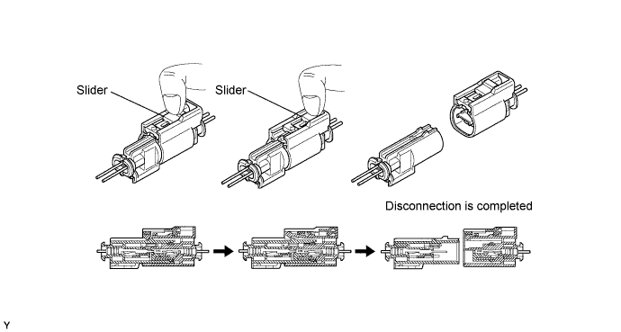
DISCONNECTION OF CONNECTORS FOR SRS SEAT CUSHION AIRBAG
-
Place a finger on the slider, slide the slider to release the lock, and then disconnect the connector.
-
-
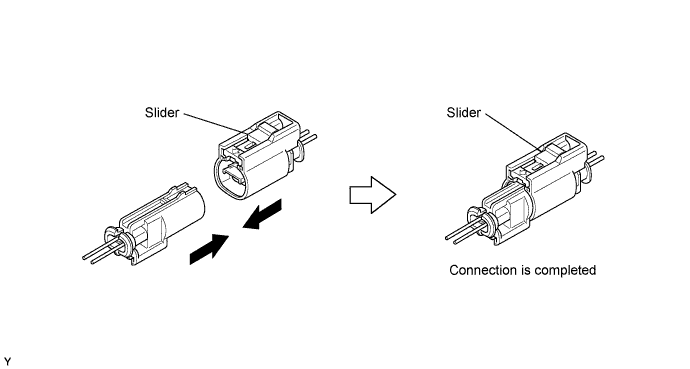
CONNECTION OF CONNECTORS FOR SRS SEAT CUSHION AIRBAG ASSEMBLY
-
Connect the connector as shown in the illustration (When locking, make sure that the slider returns to its original position and a click sound can be heard).
Tech Tips
When connecting, the slider will slide. Be sure not to touch the slider while connecting, as it may result in an insecure fit.
-
-
DISCONNECTION OF CONNECTORS FOR FRONT SEAT SIDE AIRBAG ASSEMBLY
-
Push the slider with a finger to detach the first claw. Without releasing your finger, slide the slider to detach the second claw and disconnect the connector.
-
-
CONNECTION OF CONNECTORS FOR FRONT SEAT SIDE AIRBAG ASSEMBLY
-
Connect the connector as shown in the illustration (When locking, make sure that the slider returns to its original position and click sounds can be heard).
Tech Tips
When connecting, the slider will slide. Be sure not to touch the slider while connecting, as it may result in an insecure fit.

-
-
DISCONNECTION OF CONNECTOR FOR CENTER AIRBAG SENSOR ASSEMBLY
-
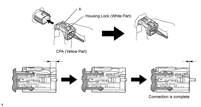
Pull the lever by pushing part A as shown in the illustration and disconnect the holder (with connectors).
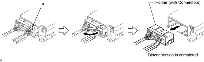
Tech Tips
Perform the following procedures when replacing the holder.
-
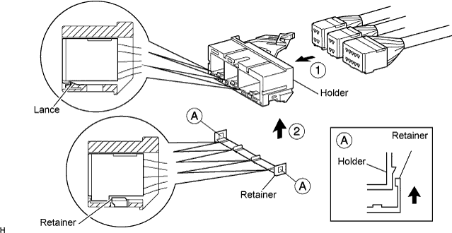
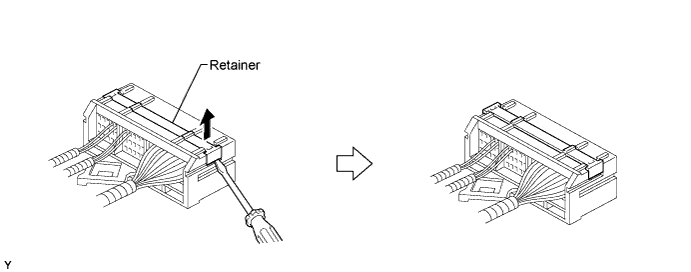
Remove the holder.
-
Using a screwdriver, unlock the retainer.
-
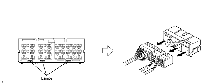
Release the fitting lances and remove the holder.
-
-
Install the holder.
-
Install the connectors into the holder. When locking, a click sound can be heard.
Tech Tips
The retainer is locked when the holder is connected.
-
-
-
CONNECTION OF CONNECTOR FOR CENTER AIRBAG SENSOR ASSEMBLY
-
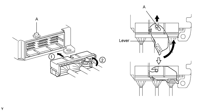
Firmly insert the holder (with connectors) into the center airbag sensor assembly until it cannot be pushed any further.
-
Push the lever to connect the holder (with connectors). When locking, a click sound can be heard.
Tech Tips
The holder slides into the center airbag sensor assembly when it is being connected. Do not hold the holder while connecting, as it may result in an insecure fit.
-
-
DISCONNECTION OF CONNECTORS FOR FRONT AIRBAG SENSOR AND REAR AIRBAG SENSOR
-
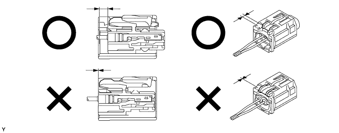
Push down the housing lock (white part) and slide the CPA (yellow part). At this time, the connector cannot be disconnected yet.
-
Push down the housing lock (white part) again and disconnect the connector.
Tech Tips
Do not push down part A shown in the illustration when disconnecting.
-
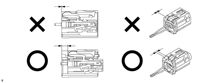
After disconnecting the connector, check that the position of the housing lock (white part) is as shown in the illustration.
-
-
CONNECTION OF CONNECTORS FOR FRONT AIRBAG SENSOR AND REAR AIRBAG SENSOR
-
Before connecting the connectors, check that the position of the housing lock (white part) is as shown in the illustration.
-
Be sure to engage the connectors until they are locked. When locking, make sure that a click sound can be heard.
Tech Tips
When connecting them, the housing lock (white part) slides. Do not hold the housing lock (white part) and part A, as it may result in an insecure fit.
-
-
DISCONNECTION OF CONNECTORS FOR SIDE AIRBAG SENSOR (FOR FRONT SIDE) AND SIDE AIRBAG SENSOR (FOR REAR SIDE)
-
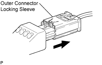
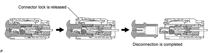
While holding the sides of the outer connector locking sleeve, slide the sleeve in the direction shown by the arrow.
-
When the connector lock is released, the connectors are disconnected.
Tech Tips
Be sure to hold both sides of the sleeve. Holding the top and bottom will make disconnection difficult.
-
-
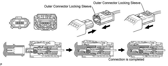
CONNECTION OF CONNECTORS FOR SIDE AIRBAG SENSOR (FOR FRONT SIDE) AND SIDE AIRBAG SENSOR (FOR REAR SIDE)
-
Connect the connector as shown in the illustration (When locking, make sure that the outer connector locking sleeve returns to its original position and a click sound can be heard).
Tech Tips
When connecting, the sleeve will slide. Be sure not to hold the sleeve while connecting, as it may result in an insecure fit.
-