THEFT DETERRENT SYSTEM Security Indicator Light Circuit
DESCRIPTION
The security indicator light comes on or blinks in response to signals received from the main body ECU.
WIRING DIAGRAM
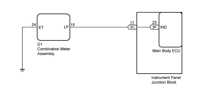
INSPECTION PROCEDURE
PROCEDURE
-
PERFORM ACTIVE TEST USING INTELLIGENT TESTER
-
Connect the intelligent tester to the DLC3.
-
Turn the ignition switch to ON.
-
Turn the intelligent tester on.
-
Enter the following menus: Body Electrical / Main Body / Active Test
-
According to the display on the tester, perform the Active Test.
Main Body Tester Display Test Part Control Range Diagnostic Note Security Indicator Security indicator light ON/OFF - OK The security indicator light blinks or goes off correctly when operating it through the intelligent tester.
NG 
CHECK HARNESS AND CONNECTOR (COMBINATION METER - INSTRUMENT PANEL J/B AND BODY GROUND) Click here
OK 
PROCEED TO NEXT SUSPECTED AREA SHOWN IN PROBLEM SYMPTOMS TABLE Click here
-
-
CHECK HARNESS AND CONNECTOR (COMBINATION METER - INSTRUMENT PANEL J/B AND BODY GROUND)
-
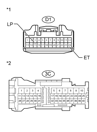
Text in Illustration *1 Front view of wire harness connector
(to Combination Meter)
*2 Front view of wire harness connector
(to Instrument Panel Junction Block)
Disconnect the D1 combination meter connector.
-
Disconnect the 3C instrument panel junction block connector.
-
Measure the resistance according to the value(s) in the table below.
Standard Resistance Tester Connection Condition Specified Condition D1-15 (LP) - 3C-17 Always Below 1 Ω D1-24 (ET) - Body ground Always Below 1 Ω D1-15 (LP) - Body ground Always 10 kΩ or higher
NG 
REPAIR OR REPLACE HARNESS OR CONNECTOR
OK 
-
-
INSPECT COMBINATION METER ASSEMBLY
-
Reconnect the 3C instrument panel junction block connector.
-
Perform Active Test using the intelligent tester to turn the security indicator to the ON state Click here.
-
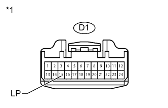
Text in Illustration *1 Front view of wire harness connector
(to Combination Meter)
Measure the voltage according to the value(s) in the table below.
Standard Voltage Tester Connection Condition Specified Condition D1-15 (LP) - Body ground Security indicator in ON state 11 to 14 V
NG
REPLACE MAIN BODY ECU Click here
OK
REPLACE COMBINATION METER ASSEMBLY Click here
-
-
REPLACE MAIN BODY ECU
-
Temporarily replace the main body ECU with a new or normally functioning one Click here.
NEXT
-
-
PERFORM ACTIVE TEST USING INTELLIGENT TESTER
-
Connect the intelligent tester to the DLC3.
-
Turn the ignition switch to ON.
-
Turn the intelligent tester on.
-
Enter the following menus: Body Electrical / Main Body / Active Test
-
According to the display on the tester, perform the Active Test.
Main Body Tester Display Test Part Control Range Diagnostic Note Security Indicator Security indicator light ON/OFF - OK The security indicator light blinks or goes off correctly when operating it through the intelligent tester.
NG
REPLACE INSTRUMENT PANEL JUNCTION BLOCK
OK
END (MAIN BODY ECU IS DEFECTIVE)
-