THEFT DETERRENT SYSTEM Security Horn Circuit
DESCRIPTION
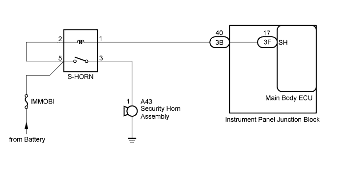
When the theft deterrent system is switched from the armed state to the alarm sounding state, the main body ECU controls the security horn.
WIRING DIAGRAM
INSPECTION PROCEDURE
Note
Inspect the fuses for circuits related to this system before performing the following inspection procedure
PROCEDURE
-
PERFORM ACTIVE TEST USING INTELLIGENT TESTER
-
Connect the intelligent tester to the DLC3.
-
Turn the ignition switch to ON.
-
Turn the intelligent tester on.
-
Enter the following menus: Body Electrical / Main Body / Active Test.
-
According to the display on the tester, perform the Active Test.
Main Body Tester Display Test Part Control Range Diagnostic Note Security Horn Security Horn ON/OFF - OK The security horn sounds and stops correctly when operating it through the intelligent tester.
NG 
INSPECT SECURITY HORN ASSEMBLY Click here
OK 
PROCEED TO NEXT SUSPECTED AREA SHOWN IN PROBLEM SYMPTOMS TABLE Click here
-
-
INSPECT SECURITY HORN ASSEMBLY
-
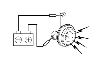
Remove the security horn assembly Click here.
-
Connect a positive battery lead to terminal 1 of the security horn assembly, and a negative battery lead to the horn body.
-
Check operation of the horn.
OK Measurement Condition Specified Condition Battery positive (+) → Terminal 1 Horn sounds Battery negative (-) → Horn body
NG 
REPLACE SECURITY HORN ASSEMBLY Click here
OK 
-
-
INSPECT S-HORN RELAY
-
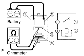
Remove the S-HORN relay.
-
Measure the resistance according to the value(s) in the table below.
Standard Resistance Tester Connection Condition Specified Condition 3 - 5 Voltage is not applied between terminals 1 and 2 10 kΩ or higher Apply the battery voltage between terminals 1 and 2 Below 1 Ω
NG
REPLACE S-HORN RELAY
OK
-
-
CHECK HARNESS AND CONNECTOR (S-HORN RELAY - SECURITY HORN ASSEMBLY)
-
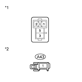
Text in Illustration *1 Front view of wire harness connector
(to S-HORN relay)
*2 Front view of wire harness connector
(to Security Horn)
Disconnect the A43 security horn assembly connector.
-
Measure the resistance according to the value(s) in the table below.
Standard Resistance Tester Connection Condition Specified Condition 3 - A43-1 Always Below 1 Ω A43-1 - Body ground Always 10 kΩ or higher
NG
REPAIR OR REPLACE HARNESS OR CONNECTOR
OK
-
-
CHECK HARNESS AND CONNECTOR (BATTERY - S-HORN RELAY)
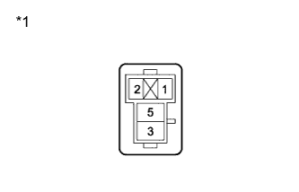
Text in Illustration *1 Front view of wire harness connector
(to S-HORN relay)
-
Measure the voltage on the junction block side according to the value(s) in the table below.
Standard Voltage Tester Connection Condition Specified Condition 2 - Body ground Always 11 to 14 V 5 - Body ground Always 11 to 14 V
NG
REPAIR OR REPLACE HARNESS OR CONNECTOR
OK
-
-
CHECK HARNESS AND CONNECTOR (S-HORN RELAY - INSTRUMENT PANEL J/B)
-

Text in Illustration *1 Front view of wire harness connector
(to S-HORN relay)
*2 Front view of wire harness connector
(to Instrument Panel Junction Block)
Disconnect the 3B instrument panel junction block connector.
-
Measure the resistance according to the value(s) in the table below.
Standard Resistance Tester Connection Condition Specified Condition 3B-40 - 1 Always Below 1 Ω 3B-40 - Body ground Always 10 kΩ or higher
NG
REPAIR OR REPLACE HARNESS OR CONNECTOR
OK
-
-
REPLACE MAIN BODY ECU
-
Temporarily replace the main body ECU with a new or normally functioning one Click here.
NEXT
-
-
PERFORM ACTIVE TEST USING INTELLIGENT TESTER
-
Connect the intelligent tester to the DLC3.
-
Turn the ignition switch to ON.
-
Turn the intelligent tester on.
-
Enter the following menus: Body Electrical / Main Body / Active Test.
-
According to the display on the tester, perform the Active Test.
Main Body Tester Display Test Part Control Range Diagnostic Note Security Horn Security Horn ON/OFF - OK The security horn sounds and stops correctly when operating it through the intelligent tester.
NG
REPLACE INSTRUMENT PANEL JUNCTION BLOCK
OK
END (MAIN BODY ECU IS DEFECTIVE)
-