THEFT DETERRENT SYSTEM Horn Circuit
DESCRIPTION
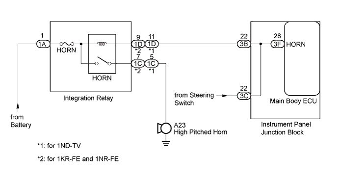
When the theft deterrent system is switched from the armed state to the alarm sounding state, the main body ECU transmits a signal to cause the horn to sound at 0.4-second intervals.
WIRING DIAGRAM
INSPECTION PROCEDURE
Note
Inspect the fuses for circuits related to this system before performing the following inspection procedure.
PROCEDURE
-
INSPECT HORNS
-
Press the horn switch and check if the horns sound.
Result Result Proceed to Horns sound A Horns do not sound B
B 
GO TO HORN SYSTEM Click here
A 
-
-
PERFORM ACTIVE TEST USING INTELLIGENT TESTER
-
Connect the intelligent tester to the DLC3.
-
Turn the ignition switch to ON.
-
Turn the intelligent tester on.
-
Enter the following menus: Body Electrical / Main Body / Active Test.
-
According to the display on the tester, perform the Active Test.
Main Body Tester Display Test Part Control Range Diagnostic Note Vehicle Horn Vehicle horns ON/OFF - OK The vehicle horns sound and stop correctly when operating them through the intelligent tester.
NG 
CHECK HARNESS AND CONNECTOR (INSTRUMENT PANEL JUNCTION BLOCK - INTEGRATION RELAY) Click here
OK 
PROCEED TO NEXT SUSPECTED AREA SHOWN IN PROBLEM SYMPTOMS TABLE Click here
-
-
CHECK HARNESS AND CONNECTOR (INSTRUMENT PANEL JUNCTION BLOCK - INTEGRATION RELAY)
-
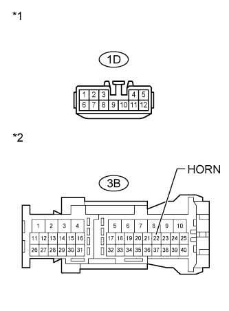
Text in Illustration *1 Front view of wire harness connector
(to Integration Relay)
*2 Front view of wire harness connector
(to Instrument Panel Junction Block)
Disconnect the 3B instrument panel junction block connector and 1D integration relay connector.
-
Measure the resistance according to the value(s) in the table below.
Standard Resistance Tester Connection Condition Specified Condition 1D-11 - 3B-22*1 Always Below 1 Ω 1D-9 - 3B-22*2 Always Below 1 Ω 3B-22 - Body ground Always 10 kΩ or higher
-
*1: for 1ND-TV
-
*2: for 1KR-FE and 1NR-FE
-
NG
REPAIR OR REPLACE HARNESS OR CONNECTOR
OK
-
-
REPLACE MAIN BODY ECU
-
Temporarily replace the main body ECU with a new or normally functioning one Click here.
NEXT
-
-
PERFORM ACTIVE TEST USING INTELLIGENT TESTER
-
Connect the intelligent tester to the DLC3.
-
Turn the ignition switch to ON.
-
Turn the intelligent tester on.
-
Enter the following menus: Body Electrical / Main Body / Active Test.
-
According to the display on the tester, perform the Active Test.
Main Body Tester Display Test Part Control Range Diagnostic Note Vehicle Horn Vehicle horns ON/OFF - OK The vehicle horns sound and stop correctly when operating them through the intelligent tester.
NG
REPLACE INSTRUMENT PANEL JUNCTION BLOCK
OK
END (MAIN BODY ECU IS DEFECTIVE)
-