THEFT DETERRENT SYSTEM Engine Hood Courtesy Switch Circuit
DESCRIPTION
The engine hood courtesy switch is installed together with the hood lock. This switch turns off when the engine hood is opened and turns on when the engine hood is closed.
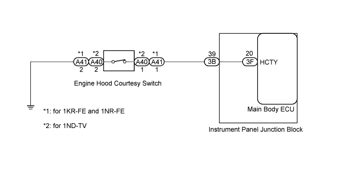
WIRING DIAGRAM
INSPECTION PROCEDURE
PROCEDURE
-
READ VALUE USING INTELLIGENT TESTER
-
Connect the intelligent tester to the DLC3.
-
Turn the ignition switch to ON
-
Turn the intelligent tester on.
-
Enter the following menus: Body Electrical / Main Body / Data List.
-
According to the display on the intelligent tester, read the Data List.
Main Body Tester Display Measurement Item/Range Normal Condition Diagnostic Note Hood Courtesy Switch Engine hood courtesy switch signal/ON or OFF ON: Engine hood is OPEN
OFF: Engine hood is CLOSED
- OK The indicator on the intelligent tester switches between ON and OFF in accordance with the engine hood courtesy switch status.
NG 
INSPECT ENGINE HOOD COURTESY SWITCH Click here
OK 
PROCEED TO NEXT SUSPECTED AREA SHOWN IN PROBLEM SYMPTOMS TABLE Click here
-
-
INSPECT ENGINE HOOD COURTESY SWITCH
-
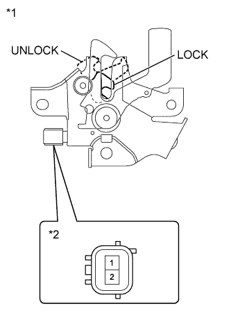
Text in Illustration *1 Engine Hood Lock Assembly *2 Component without harness connected
(Engine Hood Courtesy Switch)
Disconnect the A40 or A41 courtesy switch connector.
-
Measure the resistance according to the value(s) in the table below.
Standard Resistance Tester Connection Switch Condition Specified Condition 1 - 2 LOCK position Below 1 Ω UNLOCK position 10 kΩ or higher
NG 
REPLACE HOOD LOCK ASSEMBLY Click here
OK 
-
-
CHECK HARNESS AND CONNECTOR (ENGINE HOOD COURTESY SWITCH - BODY GROUND)
-
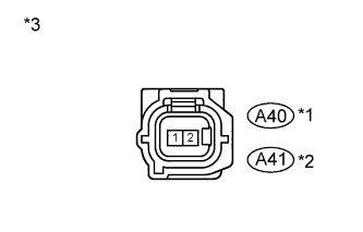
Text in Illustration *1 for 1KR-FE and 1NR-FE *2 for 1ND-TV *3 Front view of wire harness connector
(to Engine Hood Courtesy Switch)
Measure the resistance according to the value(s) in the table below.
Standard Resistance Tester Connection Condition Specified Condition A40-2 - Body ground*1 Always Below 1 Ω A41-2 - Body ground*2 Always Below 1 Ω
-
*1: for 1KR-FE and 1NR-FE
-
*2: for 1ND-TV
-
NG
REPAIR OR REPLACE HARNESS OR CONNECTOR
OK
-
-
CHECK HARNESS AND CONNECTOR (JUNCTION BLOCK - ENGINE HOOD COURTESY SWITCH)
-
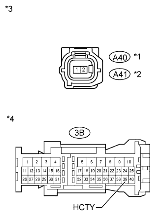
Text in Illustration *1 for 1KR-FE and 1NR-FE *2 for 1ND-TV *3 Front view of wire harness connector
(to Engine Hood Courtesy Switch)
*4 Front view of wire harness connector
(to Instrument Panel Junction Block)
Disconnect the 3B instrument panel junction block connector.
-
Measure the resistance according to the value(s) in the table below.
Standard Resistance Tester Connection Condition Specified Condition 3B-39 (HCTY) - A40-1*1 Always Below 1 Ω 3B-39 (HCTY) - A41-1*2 Always Below 1 Ω 3B-39 (HCTY) - Body ground Always 10 kΩ or higher
-
*1: for 1KR-FE and 1NR-FE
-
*2: for 1ND-TV
-
NG
REPAIR OR REPLACE HARNESS OR CONNECTOR
OK
-
-
REPLACE MAIN BODY ECU
-
Temporarily replace the main body ECU with a new or normally functioning one Click here.
NEXT
-
-
READ VALUE USING INTELLIGENT TESTER
-
Connect the intelligent tester to the DLC3.
-
Turn the ignition switch to ON
-
Turn the intelligent tester on.
-
Enter the following menus: Body Electrical / Main Body / Data List.
-
According to the display on the intelligent tester, read the Data List.
Main Body Tester Display Measurement Item/Range Normal Condition Diagnostic Note Hood Courtesy Switch Engine hood courtesy switch signal/ON or OFF ON: Engine hood is OPEN
OFF: Engine hood is CLOSED
- OK The indicator on the intelligent tester switches between ON and OFF in accordance with the engine hood courtesy switch status.
NG
REPLACE INSTRUMENT PANEL JUNCTION BLOCK
OK
END (MAIN BODY ECU IS DEFECTIVE)
-