ENGINE IMMOBILISER SYSTEM (w/o Entry and Start System), Diagnostic DTC:B2784

| DTC Code | DTC Name |
|---|---|
| B2784 | Antenna Coil Open / Short |
DESCRIPTION
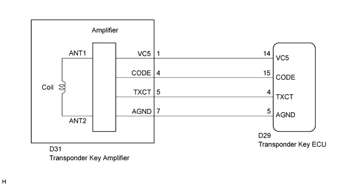
The antenna coil receives key code signals from the transponder chip in the key grip, the coil is built in to the transponder key amplifier, which amplifies the key code signals and outputs the signals to the transponder key ECU. This DTC is stored when there is an open or short in the antenna coil.
| DTC No. | DTC Detection Condition | Trouble Area |
|---|---|---|
| B2784 | When performing immobiliser set/unset, the antenna coil circuit is opened or shorted for 5 seconds. |
|
WIRING DIAGRAM
INSPECTION PROCEDURE
Note
If the transponder key ECU is replaced, register the key and ECU - ECM communication ID.
PROCEDURE
-
CHECK HARNESS AND CONNECTOR (TRANSPONDER KEY ECU - TRANSPONDER KEY AMPLIFIER)
-
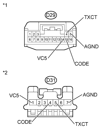
Text in Illustration *1 Front view of wire harness connector
(to Transponder Key ECU)
*2 Front view of wire harness connector
(to Transponder Key Amplifier)
Disconnect the D29 transponder key ECU connectors.
-
Disconnect the D24 transponder key amplifier connector.
-
Measure the resistance according to the value(s) in the table below.
Standard Resistance Tester Connection Condition Specified Condition D29-4 (TXCT) - D31-5 (TXCT) Always Below 1 Ω D29-5 (AGND) - D31-7 (AGND) Always Below 1 Ω D29-14 (VC5) - D31-1 (VC5) Always Below 1 Ω D29-15 (CODE) - D31-4 (CODE) Always Below 1 Ω D29-4 (TXCT) - Body ground Always 10 kΩ or higher D29-5 (AGND) - Body ground Always 10 kΩ or higher D29-14 (VC5) - Body ground Always 10 kΩ or higher D29-15 (CODE) - Body ground Always 10 kΩ or higher -
Reconnect the amplifier and ECU connector.
NG 
REPAIR OR REPLACE HARNESS OR CONNECTOR
OK 
-
-
INSPECT TRANSPONDER KEY ECU (TRANSPONDER KEY AMPLIFIER POWER SOURCE AND GROUND)
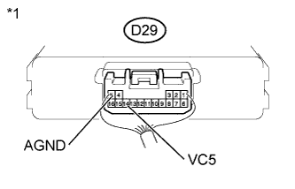
Text in Illustration *1 Component with harness connected
(Transponder Key ECU)
-
Measure the voltage and resistance according to the value(s) in the table below.
Standard Voltage Tester Connection Condition Specified Condition D29-14 (VC5) - Body ground No key is in ignition key cylinder Below 1 V Key is in ignition key cylinder 4.6 to 5.4 V D29-5 (AGND) - Body ground Always Below 1 Ω -
Measure the resistance according to the value(s) in the table below.
Standard Resistance Tester Connection Condition Specified Condition D29-5 (AGND) - Body ground Always Below 1 Ω
NG
REPLACE TRANSPONDER KEY ECU
OK
-
-
REPLACE TRANSPONDER KEY AMPLIFIER
-
Temporarily replace the transponder key amplifier with a new or normally functioning one Click here.
NEXT
-
-
CLEAR DTC
-
Clear the DTC Click here.
NEXT
-
-
CHECK FOR DTC
-
Check for DTCs Click here.
OK DTC B2784 is not output.
NG
REPLACE TRANSPONDER KEY ECU
OK 
END (TRANSPONDER KEY AMPLIFIER IS DEFECTIVE)
-