ENGINE IMMOBILISER SYSTEM (w/o Entry and Start System) TERMINALS OF ECU

-
CHECK TRANSPONDER KEY AMPLIFIER
-
Disconnect the D31 amplifier connector and measure the resistance according to the value(s) in the table below.

Terminal No. (Symbol) Wiring Color Terminal Description Condition Specified Condition D31-7 (AGND) - Body ground R - Body ground Ground Always Below 1 Ω If the result is not as specified, there may be a malfunction on the wire harness side.
-
Reconnect the D31 amplifier connector and measure the voltage according to the value(s) in the table below.
Terminal No. (Symbol) Wiring Color Terminal Description Condition Specified Condition D31-1 (VC5) - D31-7 (AGND) Y - R Power source No key is in ignition key cylinder Below 1 V Key is in ignition key cylinder 4.6 to 5.4 V D31-4 (CODE) - D31-7 (AGND) L - R Demodulated signal of key code data No key is in ignition key cylinder Below 1 V Key is in ignition key cylinder Waveform 1 D31-5 (TXCT) - D31-7 (AGND) W - R Key code output signal No key is in ignition key cylinder Below 1 V Key is in ignition key cylinder Waveform 2 If the result is not as specified, the amplifier may have a malfunction.
-
Inspect using an oscilloscope.
-
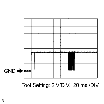
Waveform 1
Tester Connection D31-4 (CODE) - D31-7 (AGND) Tool Setting 2 V/DIV., 20 ms./DIV. Condition Key is in ignition key cylinder -
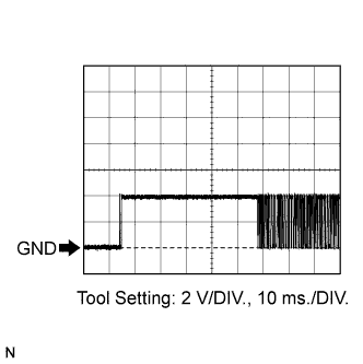
Waveform 2
Tester Connection D31-5 (TXCT) - D31-7 (AGND) Tool Setting 2 V/DIV., 10 ms./DIV. Condition Key is in ignition key cylinder
-
-
-
CHECK TRANSPONDER KEY ECU
-
Disconnect the D29 ECU connector and measure the resistance and voltage according to the value(s) in the table below.

Terminal No. (Symbol) Wiring Color Terminal Description Condition Specified Condition D29-16 (GND) - Body ground W-B - Body ground Ground Always Below 1 Ω D29-1 (+B) - D29-16 (GND) Y - W-B Battery Always 11 to 14 V D29-2 (IG) - D29-16 (GND) V - W-B Ignition switch signal Ignition switch off Below 1 V Ignition switch ON 11 to 14 V D29-3 (KSW) - D29-16 (GND) SB - W-B*1
LG - W-B*2
Unlock warning switch signal No key is in ignition key cylinder 10 kΩ or higher Key is in ignition key cylinder Below 1 Ω
-
*1: for LHD
-
*2: for RHD
If the result is not as specified, there may be a malfunction on the wire harness side.
-
-
Reconnect the D29 ECU connector and measure the resistance and voltage according to the value(s) in the table below.
Terminal No. (Symbol) Wiring Color Terminal Description Condition Specified Condition D29-5 (AGND) - Body ground R - Body ground Ground Always Below 1 Ω D29-3 (KSW) - D29-16 (GND) SB - W-B*1
LG - W-B*2
Unlock warning switch signal No key is in ignition key cylinder 11 to 14 V Key is in ignition key cylinder Below 1 V D29-14 (VC5) - D29-5 (AGND) Y - R Power source No key is in ignition key cylinder Below 1 V Key is in ignition key cylinder 4.6 to 5.4 V D29-4 (TXCT) - D29-5 (AGND) W - R Transponder key amplifier communication signal No key is in ignition key cylinder Below 1 V Key is in ignition key cylinder Waveform 1 D29-15 (CODE) - D29-5 (AGND) L - R Transponder key amplifier communication signal No key is in ignition key cylinder Below 1 V Key is in ignition key cylinder Waveform 2 D29-13 (EFIO) - D29-16 (GND) BR - W-B*1
LG - W-B*2
ECM output signal Ignition switch off Below 1 V Ignition switch ON Waveform 3 D29-12 (EFII) - D29-16 (GND) GR - W-B*1
LG - W-B*2
ECM input signal Ignition switch off Below 1 V Ignition switch ON Waveform 4 D29-9 (D) - D29-16 (GND) R - W-B*1
LG - W-B*2
Diagnostic tester communication Without communication Below 1 V During communication Pulse generation D29-7 (CTY) - D29-16 (GND) LG - W-B Door courtesy signal Switch pushed 11 to 14 V Switch free Below 1 V
-
*1: for LHD
-
*2: for RHD
If the result is not as specified, the ECU may have a malfunction.
-
-
Inspect using an oscilloscope.
-
Waveform 1
Tester Connection D29-4 (TXCT) - D29-5 (AGND) Tool Setting 2 V/DIV., 10 ms./DIV. Condition Key is in ignition key cylinder -
Waveform 2
Tester Connection D29-15 (CODE) - D29-5 (AGND) Tool Setting 2 V/DIV., 20 ms./DIV. Condition Key is in ignition key cylinder -
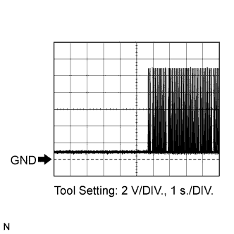
Waveform 3
Tester Connection D29-13 (EFIO) - D29-16 (GND) Tool Setting 2 V/DIV., 1 s./DIV. Condition Ignition switch ON -
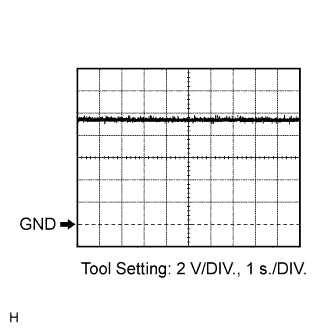
Waveform 4
Tester Connection D29-12 (EFII) - D29-16 (GND) Tool Setting 2 V/DIV., 1 s./DIV. Condition Ignition switch ON
-
-
-
CHECK ECM (for 1KR-FE and 1NR-FE)
-
The values listed under "Specified Condition" are reference values. Because waterproof connectors are used for ECM, inspections can not be performed with the connectors connected.
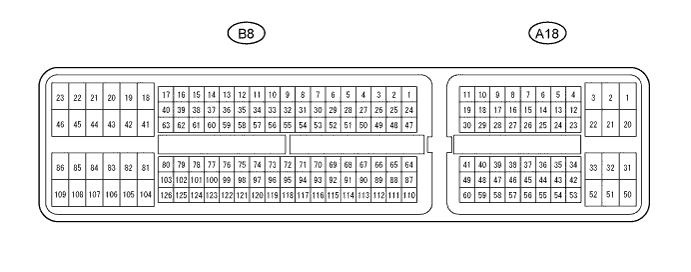
Terminal No. (Symbol) Wiring Color Terminal Description Condition Specified Condition B8-105 (E1) - Body ground BR - Body ground Ground Always Below 1 Ω A18-11 (IMI) - B8-105 (E1) G-B - BR Transponder key ECU input signal Ignition switch off Below 1 V Ignition switch ON Waveform 1 A18-10 (IMO) - B8-105 (E1) W-L - BR Transponder key ECU output signal Ignition switch off Below 1 V Ignition switch ON Waveform 2 -
Inspect using an oscilloscope.
-
Waveform 1
Tester Connection A18-11 (IMI) - B8-105 (E1) Tool Setting 2 V/DIV., 1 s./DIV. Condition Ignition switch ON -
Waveform 2
Tester Connection A18-10 (IMO) - B8-105 (E1) Tool Setting 2 V/DIV., 1 s./DIV. Condition Ignition switch ON
-
-
-
CHECK ECM (for 1ND-TV)
-
The values listed under "Specified Condition" are reference values. Because waterproof connectors are used for ECM, inspections can not be performed with the connectors connected.
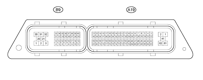
Terminal No. (Symbol) Wiring Color Terminal Description Condition Specified Condition A19-2 (E1) - Body ground W-B - Body ground Ground Always Below 1 Ω A19-77 (IMI) - A19-2 (E1) G-B - W-B Transponder key ECU input signal Ignition switch off Below 1 V Ignition switch ON Waveform 1 A19-78 (IMO) - A19-2 (E1) W-L - W-B Transponder key ECU output signal Ignition switch off Below 1 V Ignition switch ON Waveform 2 -
Inspect using an oscilloscope.
-
Waveform 1
Tester Connection A19-77 (IMI) - A19-2 (E1) Tool Setting 2 V/DIV., 1 s./DIV. Condition Ignition switch ON -
Waveform 2
Tester Connection A19-78 (IMO) - A19-2 (E1) Tool Setting 2 V/DIV., 1 s./DIV. Condition Ignition switch ON
-
-