LIGHTING SYSTEM Illumination Circuit
DESCRIPTION
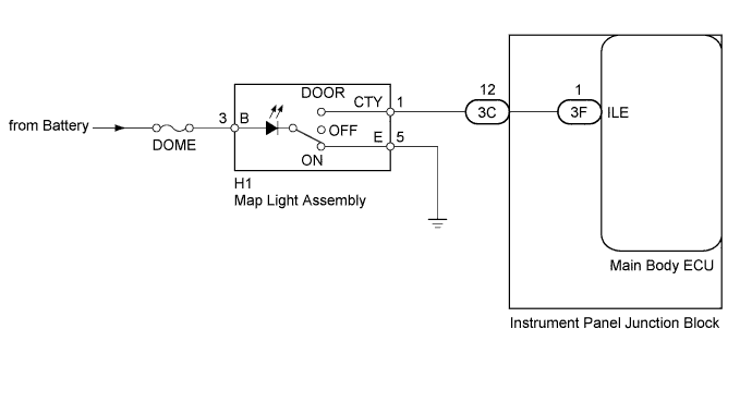
The main body ECU receives information regarding the door courtesy switch and door lock position switch, and turns on the map light assembly.
WIRING DIAGRAM
INSPECTION PROCEDURE
Note
Inspect the fuses for circuits related to this system before performing the following inspection procedure.
PROCEDURE
-
PERFORM ACTIVE TEST USING INTELLIGENT TESTER (ILLUMINATED ENTRY SYSTEM)
-
Connect the intelligent tester to the DLC3.
-
Turn the ignition switch to ON.
-
Turn the tester on.
-
Turn the room light switch to the DOOR position.
-
All doors closed (door courtesy switches OFF).
-
Enter the following menus: Body / Main Body / Active Test.
-
According to the display on the tester, perform the Active Test.
Main Body Tester Display Test Part Control Range Normal Condition Illuminated Entry System Map light assembly ON/OFF - OK The illuminated entry system operates normally when operating it through the intelligent tester.
NG 
CHECK HARNESS AND CONNECTOR (MAP LIGHT ASSEMBLY - BATTERY AND BODY GROUND) Click here
OK 
PROCEED TO NEXT SUSPECTED AREA SHOWN IN PROBLEM SYMPTOMS TABLE Click here
-
-
CHECK HARNESS AND CONNECTOR (MAP LIGHT ASSEMBLY - BATTERY AND BODY GROUND)
-
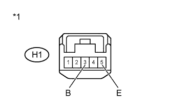
Text in Illustration *1 Front view of wire harness connector
(to Map Light Assembly)
Disconnect the H1 map light assembly connector.
-
Measure the voltage according to the value(s) in the table below.
Standard Voltage Tester Connection Switch Condition Specified Condition H1-3 (B) - Body ground Map light switch in ON position 11 to 14 V -
Measure the resistance according to the value(s) in the table below.
Standard Resistance Tester Connection Condition Specified Condition H1-5 (E) - Body ground Always Below 1 Ω -
Reconnect the map light assembly connector.
NG 
REPAIR OR REPLACE HARNESS OR CONNECTOR
OK 
-
-
INSPECT MAP LIGHT ASSEMBLY
-

Text in Illustration *1 Component without harness connected
(Map Light Assembly)
Remove the map light assembly.
-
Measure the resistance according to the value(s) in the table below.
Standard Resistance DC 13.5 V Tester Connection Switch Condition Specified Condition 3 (B) - 1 (CTY)
3 (B) - 5 (E)
OFF 10 kΩ or higher 3 (B) - 1 (CTY) DOOR Below 400 Ω 3 (B) - 5 (E) ON Below 400 Ω -
Reinstall the map light assembly.
NG
REPLACE MAP LIGHT ASSEMBLY Click here
OK
-
-
CHECK HARNESS AND CONNECTOR (INSTRUMENT PANEL JUNCTION BLOCK - MAP LIGHT ASSEMBLY)
-
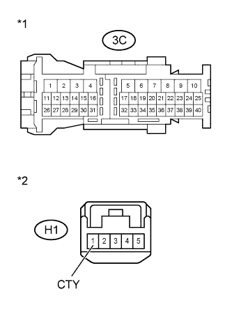
Text in Illustration *1 Front view of wire harness connector
(to Instrument Panel Junction Block)
*2 Front view of wire harness connector
(to Map Light Assembly)
Disconnect the 3C instrument panel junction block connector.
-
Disconnect the map light assembly connector.
-
Measure the resistance according to the value(s) in the table below.
Standard Resistance Tester Connection Condition Specified Condition 3C-12 - H1-1 (CTY) Always Below 1 Ω 3C-12 or H1-1 (CTY) - Body ground Always 10 kΩ or higher -
Reconnect the instrument panel junction block connector.
-
Reconnect the map light assembly connector.
NG
REPAIR OR REPLACE HARNESS OR CONNECTOR
OK
-
-
REPLACE MAIN BODY ECU
-
Temporarily replace the main body ECU with a new or normally functioning one Click here.
NEXT
-
-
CHECK ILLUMINATED ENTRY SYSTEM
-
Check if the illuminated entry system operates correctly Click here.
OK System operates correctly.
NG
REPLACE INSTRUMENT PANEL JUNCTION BLOCK
OK
END (MAIN BODY ECU IS DEFECTIVE)
-