LIGHTING SYSTEM Door Courtesy Switch Circuit
DESCRIPTION
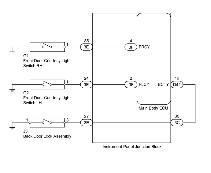
The main body ECU receives a door open/closed signal from each door courtesy switch.
WIRING DIAGRAM
INSPECTION PROCEDURE
PROCEDURE
-
READ VALUE USING INTELLIGENT TESTER
-
Connect the intelligent tester to the DLC3.
-
Turn the ignition switch to ON.
-
Turn the tester on.
-
Enter the following menus: Body / Main Body / Data List.
-
According to the display on the tester, read the Data List.
Main Body Tester Display Measurement Item/Range Normal Condition Diagnostic Note Back Door Courtesy SW Back door courtesy switch signal/ ON or OFF ON: Back door is open
OFF: Back door is closed
- FR Door Courtesy SW Front RH door courtesy switch signal/ ON or OFF ON: Front RH door is open
OFF: Front RH door door is closed
- FL Door Courtesy SW Front LH door courtesy switch signal/ ON or OFF ON: Front LH door is open
OFF: Front LH door is closed
- OK Normal conditions listed above are displayed.
NG 
INSPECT DOOR COURTESY SWITCH Click here
OK 
PROCEED TO NEXT SUSPECTED AREA SHOWN IN PROBLEM SYMPTOMS TABLE Click here
-
-
INSPECT DOOR COURTESY SWITCH
-
Inspect the front door courtesy light switch Click here, back door courtesy switch Click here.
OK Door courtesy switches are normal. Result Result Proceed to OK A NG (Front door courtesy light switch) B NG (Back door courtesy switch) C
B 
REPLACE FRONT DOOR COURTESY LIGHT SWITCH Click here
C
REPLACE BACK DOOR LOCK ASSEMBLY Click here
A 
-
-
CHECK HARNESS AND CONNECTOR (DOOR COURTESY SWITCH - JUNCTION BLOCK AND BODY GROUND)
-
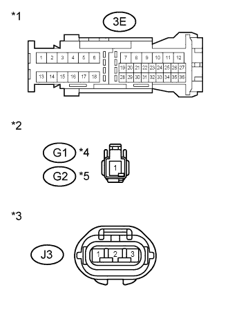
Text in Illustration *1 Front view of wire harness connector
(to Instrument Panel Junction Block)
*2 Front view of wire harness connector
(to Front Door Courtesy Light Switch)
*3 Front view of wire harness connector
(to Back Door Lock Assembly)
*4 Front RH *5 Front LH Disconnect the 3E instrument panel junction block connector.
-
Disconnect G1 and G2 front door courtesy light switch connector.
-
Disconnect the J3 back door lock assembly connector.
-
Measure the resistance according to the value(s) in the table below.
Standard Resistance Front RH Side Tester Connection Condition Specified Condition 3E-35 - G1-1 Always Below 1 Ω G1-1 - Body ground Always 10 kΩ or higher Front LH Side Tester Connection Condition Specified Condition 3E-24 - G2-1 Always Below 1 Ω G2-1 - Body ground Always 10 kΩ or higher Back Door Tester Connection Condition Specified Condition 3E-27 - J3-3 Always Below 1 Ω J3-3 - Body ground Always 10 kΩ or higher J3-1 - Body ground Always Below 1 Ω -
Reconnect the instrument panel junction block connector.
-
Reconnect front door courtesy light switch connector.
-
Reconnect the back door lock assembly connector.
NG
REPAIR OR REPLACE HARNESS OR CONNECTOR
OK
-
-
CHECK HARNESS AND CONNECTOR (INSTRUMENT PANEL JUNCTION BLOCK - MAIN BODY ECU)
-
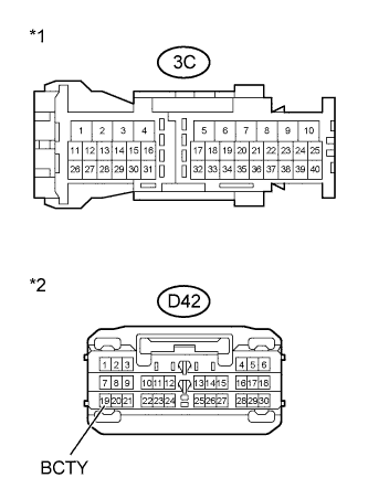
Text in Illustration *1 Front view of wire harness connector
(to Instrument Panel Junction Block)
*2 Front view of wire harness connector
(to Main Body ECU)
Disconnect the 3C instrument panel junction block connector.
-
Disconnect the D42 main body ECU connector.
-
Measure the resistance according to the value(s) in the table below.
Standard Resistance Tester Connection Condition Specified Condition 3C-30 - D42-19 (BCTY) Always Below 1 Ω 3C-30 or D42-19 (BCTY) - Body ground Always 10 kΩ or higher -
Reconnect the instrument panel junction block connector.
-
Reconnect the main body ECU connector.
NG
REPAIR OR REPLACE HARNESS OR CONNECTOR
OK
-
-
REPLACE MAIN BODY ECU
-
Temporarily replace the main body ECU with a new or normally functioning one Click here.
NEXT
-
-
READ VALUE USING INTELLIGENT TESTER
-
Connect the intelligent tester to the DLC3.
-
Turn the ignition switch to ON.
-
Turn the tester on.
-
Enter the following menus: Body / Main Body / Data List.
-
According to the display on the tester, read the Data List.
Main Body Tester Display Measurement Item/Range Normal Condition Diagnostic Note Back Door Courtesy SW Back door courtesy switch signal/ ON or OFF ON: Back door is open
OFF: Back door is closed
- FR Door Courtesy SW Front RH door courtesy switch signal/ ON or OFF ON: Front RH door is open
OFF: Front RH door door is closed
- FL Door Courtesy SW Front LH door courtesy switch signal/ ON or OFF ON: Front LH door is open
OFF: Front LH door is closed
- OK Normal conditions listed above are displayed.
NG
REPLACE INSTRUMENT PANEL JUNCTION BLOCK
OK
END (MAIN BODY ECU IS DEFECTIVE)
-