LIGHTING SYSTEM TERMINALS OF ECU

-
CHECK MAIN BODY ECU AND INSTRUMENT PANEL JUNCTION BLOCK
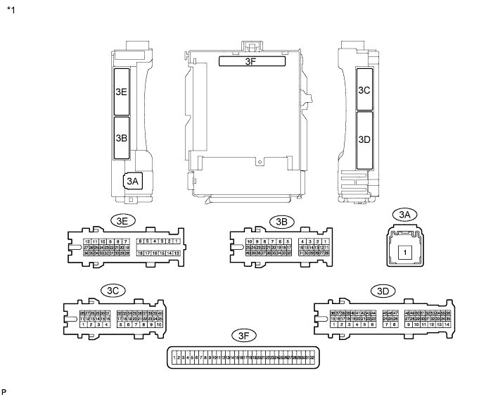
Text in Illustration *1 Instrument Panel Junction Block 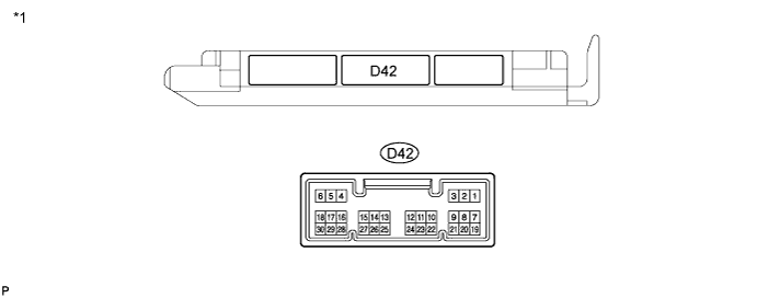
Text in Illustration *1 Main body ECU (w/ Theft Deterrent System) 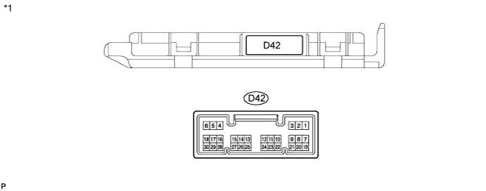
Text in Illustration *1 Main body ECU (w/o Theft Deterrent System)
-
Remove the main body ECU.
-
Disconnect the D42 main body ECU connector.
-
Measure the resistance and voltage between each terminal of the wire harness side connectors and body ground.
Terminal No. (Symbol) Wiring Color Terminal Description Condition Specified Condition 3F-11 (GND1) - Body ground - Ground Always Below 1 Ω 3F-29 (ACC)*1 - Body ground - Ignition power supply (ACC signal) Ignition switch ACC → off 11 to 14 V → Below 1 V 3F-30 (BECU) - Body ground - +B (power system signal system) power supply Always 11 to 14 V 3F-32 (IG)*1 - Body ground - Ignition power supply (IG signal) Ignition switch ON → off 11 to 14 V → Below 1 V D42-19 (BCTY) - Body ground V - Body ground Back door courtesy switch input Back door CLOSED → OPEN 10 kΩ or higher → Below 1 Ω
-
*1: w/o Entry and Start System
If the result is not as specified, there may be a malfunction on the wire harness side.
-
-
Reinstall the main body ECU.
-
Reconnect the main body ECU connector.
-
Measure the voltage between each terminal of the wire harness side connectors and body ground.
Terminal No. (Symbol) Wiring Color Terminal Description Condition Specified Condition 3C-12 (ILE) - Body ground B - Body ground Illumination signal (to map light assembly) Map light switch in DOOR position and map light assembly comes on 11 to 14 V Map light switch in OFF position and map light assembly comes off Below 1 V If the result is not as specified, the main body ECU may have a malfunction.
-