ENTRY AND START SYSTEM (for Start Function) Engine does not Start
DESCRIPTION
-
ENGINE START SYSTEM FUNCTION
-
for Continuously Variable Transaxle: If the engine switch is pressed with the shift lever in P or N and the brake pedal depressed, the power management control ECU*1 or power source control ECU*2 determines that it is an engine start request.
for Manual Transaxle: If the engine switch is pressed with the clutch pedal depressed, the power management control ECU*1 or power source control ECU*2 determines that it is an engine start request.
-
The certification ECU (smart key ECU assembly) and other ECUs perform key verification via the LIN communication line.
-
The power management control ECU*1 or power source control ECU*2 activates the ACC relay.
-
The power management control ECU*1 or power source control ECU*2 activates the IG1 and IG2 relays.
-
The certification ECU (smart key ECU assembly) outputs a steering UNLOCK signal. The signal is sent to the power management control ECU*1 or power source control ECU*2 via the steering lock ECU.
-
The ECM and power management control ECU*1 or power source control ECU*2 activate the starter relay.
-
The power management control ECU*1 or power source control ECU*2 deactivates the ACC relay until the power management control ECU*1 or power source control ECU*2 detects an engine start.
*1: for 1KR-FE and 1NR-FE
*2: for 1ND-TV
-
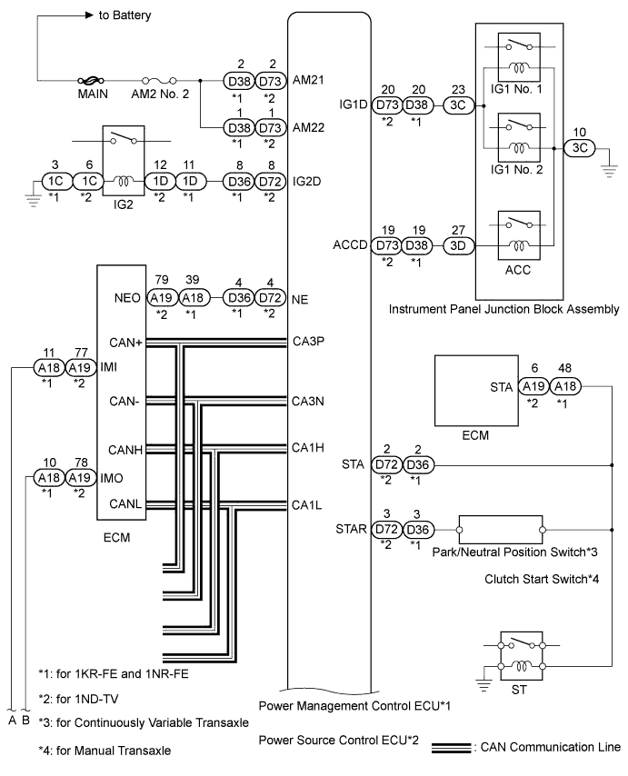
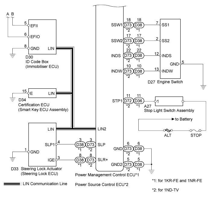
WIRING DIAGRAM
INSPECTION PROCEDURE
-
EMERGENCY ENGINE START CONTROL
-
for Continuously Variable Transaxle: If there is a malfunction in the stop light switch assembly or STOP fuse, the signals may not be correctly transmitted to the power management control ECU*1 or power source control ECU*2. This may result in the engine not starting even if the engine switch is pressed while the brake pedal is depressed and the shift lever is in P.
for Manual Transaxle: If there is a malfunction in the stop light switch assembly or STOP fuse, the signals may not be correctly transmitted to the power management control ECU*1 or power source control ECU*2. This may result in the engine not starting even if the engine switch is pressed while the brake pedal and clutch pedal are depressed.
To activate the starter:
-
Turn the engine switch from off to on (ACC).
-
Press and hold the engine switch for 15 seconds.
-
Tech Tips
After the certification ECU (smart key ECU assembly), steering lock actuator assembly (steering lock ECU), ID code box (immobiliser code ECU) and/or ECM are/is replaced, perform the registration procedures for the engine immobiliser system.
-
*1: for 1KR-FE and 1NR-FE
-
*2: for 1ND-TV
-
PROCEDURE
-
CHECK IF ENGINE STARTS
-
for Continuously Variable Transaxle: Place the electrical key on the seat. Move the shift lever to P. Step on the brake pedal.
for Manual Transaxle: Place the electrical key on the seat. Step on the clutch pedal.
-
Check that the engine switch indicator is illuminated in green, push the engine switch, and check that the engine starts.
-
Open and close the driver's door with the engine switch off.
-
Check if the engine can be started.
OK Engine can be started. Tech Tips
After the battery is discharged and then recharged or replaced, the engine may not start unless the steering lock is initialized using the above procedure.
NG 
READ VALUE USING INTELLIGENT TESTER AND CHECK FOR DTC Click here
OK 
USE SIMULATION METHOD TO CHECK Click here
-
-
READ VALUE USING INTELLIGENT TESTER AND CHECK FOR DTC
-
Read value using intelligent tester (Power Supply Open).
-
Connect the intelligent tester to the DLC3.
-
Turn the engine switch on (IG).
-
Turn the intelligent tester on.
-
Enter the following menus: Body / Entry & Start / Data List.
-
Read the Data List according to the display on the intelligent tester.
Entry and Start Tester Display Measurement Item/Range Normal Condition Diagnostic Note Power Supply Open Power supply open / OK or NG (Past) OK: Power supply open occurs
NG (Past): Power supply open does not occur
-
-
-
Check for DTC
-
Enter the following menus: All / DTC.
-
Read the DTC.
Result Result Proceed to No DTC output A DTC output B Power supply open occurs C
-
B 
GO TO APPLICABLE DTC CHART
C
GO TO STEERING LOCK SYSTEM (DIAGNOSTIC TROUBLE CODE CHART) Click here
A 
-
-
CHECK THE ENGINE SWITCH CONDITION
-
Check if the power source mode changes.
-
When the key is inside the vehicle and the shift lever is in P, check that the power source mode changes.
Result Result Proceed to OK: off → on (ACC) → on (IG) → off A Power Source Mode does not Change to ON (IG and ACC) B Power Source Mode does not Change to ON (IG) C Power Source Mode does not Change to ON (ACC) D
-
B
GO TO POWER SOURCE MODE DOES NOT CHANGE TO ON (IG AND ACC) Click here
C
GO TO POWER SOURCE MODE DOES NOT CHANGE TO ON (IG) Click here
D
GO TO POWER SOURCE MODE DOES NOT CHANGE TO ON (ACC) Click here
A
-
-
CHECK CRANKING FUNCTION
-
Check the engine cranking function.
-
for Continuously Variable Transaxle: When there is fuel in the fuel tank, the key is inside the vehicle, and the shift lever is in P, check that depressing the brake pedal and pressing the engine switch cranks the engine.
for Manual transaxle: When there is fuel in the fuel tank and the key is inside the vehicle, check that depressing the clutch pedal and pressing the engine switch cranks the engine.
OK Engine cranks. Result Result Proceed to OK (for 1KR-FE) A OK (for 1NR-FE) B OK (for 1ND-TV) C NG D
-
B
GO TO SFI SYSTEM Click here
C
GO TO ECD SYSTEM Click here
D
INSPECT PARK/NEUTRAL POSITION SWITCH OR CLUTCH START SWITCH Click here
A
GO TO SFI SYSTEM Click here
-
-
INSPECT PARK/NEUTRAL POSITION SWITCH OR CLUTCH START SWITCH
-
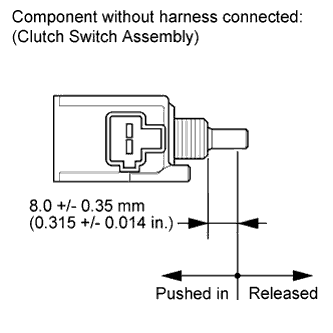
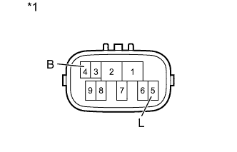
Text in Illustration *1 Component without harness connected
Park/Neutral Start Switch
for Continuously Variable Transaxle:
-
Disconnect the B13 park/neutral start switch connector.
-
Measure the resistance according to the value(s) in the table below.
Standard Resistance Tester Connection Condition Specified Condition 4 (B) - 5 (L) Shift lever in P or N Below 1 Ω Shift lever not in P or N 10 kΩ or higher
-
-
for Manual Transaxle:
-
Disconnect the A29 clutch start switch connector.
-
Measure the resistance according to the value(s) in the table below.
Standard Resistance Tester Connection Switch Condition Specified Condition 1 - 2 Pushed in
(Clutch pedal depressed)
Below 1 Ω Released
(Clutch pedal released)
10 kΩ or higher
-
NG
REPAIR OR REPLACE HARNESS OR CONNECTOR OR ST RELAY OR PARK/NEUTRAL POSITION SWITCH OR CLUTCH START SWITCH Click here
OK
-
-
INSPECT ST RELAY
-
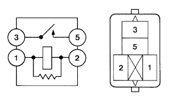
Remove the ST relay from the engine relay block.
-
Measure the resistance according value(s) in the table below.
Standard Resistance Tester Connection Condition Specified Condition 3 - 5 Battery voltage not applied 10 kΩ or higher Battery voltage applied to terminals 1 and 2 Below 1 Ω
NG
REPAIR OR REPLACE HARNESS OR CONNECTOR OR ST RELAY OR PARK/NEUTRAL POSITION SWITCH OR CLUTCH START SWITCH Click here
OK
-
-
CHECK HARNESS AND CONNECTOR (ECU - BODY GROUND)
-
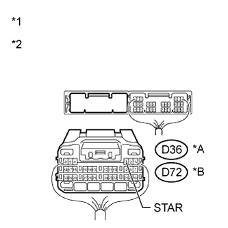
Text in Illustration *A for 1KR-FE and 1NR-FE *B for 1ND-TV *1 Rear view of wire harness connector
(to Power Management Control ECU) (for 1KR-FE and 1NR-FE)
*2 Rear view of wire harness connector
(to Power Source Control ECU) (for 1ND-TV)
Disconnect the D36 or D72 ECU connector.
-
Shift lever in P or N.
-
Measure the resistance according to the value(s) in the table below.
-
for 1KR-FE and 1NR-FE
Standard Resistance Tester Connection Condition Specified Condition D36-3 (STAR) - Body ground 20°C (68°F) 93.8 to 136.4 Ω -
for 1ND-TV
Standard Resistance Tester Connection Condition Specified Condition D72-3 (STAR) - Body ground 20°C (68°F) 93.8 to 136.4 Ω
-
NG
REPAIR OR REPLACE HARNESS OR CONNECTOR OR ST RELAY OR PARK/NEUTRAL POSITION SWITCH OR CLUTCH START SWITCH Click here
OK
-
-
READ VALUE USING INTELLIGENT TESTER (STOP LIGHT SWITCH ASSEMBLY)
-
for Continuously Variable Transaxle:
-
Connect the intelligent tester to the DLC3.
-
Turn the engine switch on (IG).
-
Turn the intelligent tester on.
-
Enter the following menus: Body / Power Source Control / Data List.
-
Read the Data List according to the display on the intelligent tester.
Power Source Control Tester Display Measurement Item/Range Normal Condition Diagnostic Note Stop Light Switch1 Stop light switch 1/ON or OFF ON: Brake pedal depressed
OFF: Brake pedal released
- OK ON (brake pedal depressed) and OFF (brake pedal released) appear on the screen.
-
-
for Manual Transaxle:
-
Connect the intelligent tester to the DLC3.
-
Turn the engine switch on (IG).
-
Turn the intelligent tester on.
-
Enter the following menus: Body / Power Source Control / Data List.
-
Read the Data List according to the display on the intelligent tester.
Power Source Control Tester Display Measurement Item/Range Normal Condition Diagnostic Note Clutch SW Clutch switch/ON or OFF ON: Clutch pedal depressed
OFF: Clutch pedal released
- OK ON (clutch pedal depressed) and OFF (clutch pedal released) appear on the screen. Result Result Proceed to OK A NG (for Continuously Variable Transaxle) B NG (for 1KR-FE and 1NR-FE Manual Transaxle) C NG (for 1ND-TV Manual Transaxle) D
-
B
C
REPLACE POWER MANAGEMENT CONTROL ECU Click here
D
REPLACE POWER SOURCE CONTROL ECU Click here
A
-
-
READ VALUE USING INTELLIGENT TESTER (STEERING UNLOCK SWITCH)
-
Connect the intelligent tester to the DLC3.
-
Turn the engine switch on (IG).
-
Turn the intelligent tester on.
-
Enter the following menus: Body / Power Source Control / Data List.
-
Read the Data List according to the display on the intelligent tester.
Power Source Control Tester Display Measurement Item/Range Normal Condition Diagnostic Note Steering Unlock Switch Steering unlock switch/ON or OFF ON: Steering unlock
OFF: Steering lock
- OK ON (steering unlock) and OFF (steering lock) appear on the screen.
NG
OK
-
-
CHECK STEERING LOCK
-
Change the engine switch from off to on (ACC) and check that the steering lock moves to the unlocked position when the engine switch is on (ACC).
OK Lock moves to unlocked position.
NG
GO TO STEERING LOCK SYSTEM Click here
OK
-
-
READ VALUE USING INTELLIGENT TESTER (L CODE)
-
Connect the intelligent tester to the DLC3.
-
Turn the intelligent tester on.
-
Enter the following menus: Body / Entry & Start / Data List.
-
Read the Data List according to the display on the intelligent tester.
Tech Tips
When using the intelligent tester with the engine switch off, turn on and off any of the door courtesy light switches repeatedly at 1.5 second intervals or less until communication between the tester and vehicle starts.
-
Turn the engine switch on (IG).
Entry and Start Tester Display Measurement Item/Range Normal Condition Diagnostic Note L Code Check L code certification result/OK or NG OK: L code certification result normal
NG: L code certification result abnormal
- OK OK (L code certification result normal) appears on the screen.
NG
GO TO ENGINE IMMOBILISER SYSTEM Click here
OK
-
-
READ VALUE USING INTELLIGENT TESTER (ENGINE START REQUEST)
-
Connect the intelligent tester to the DLC3.
-
Turn the intelligent tester on.
-
Enter the following menus: Body / Entry & Start / Data List.
-
Read the Data List according to the displays on the tester screen.
-
Turn the engine switch on (IG).
Entry & Start Tester Display Measurement Item/Range Normal Condition Diagnostic Note Engine Start Request Start request signal response/OK or NG OK: Received
NG: Not received
- OK IG on (IG) appear on the screen.
NG
REPLACE CERTIFICATION ECU (SMART KEY ECU ASSEMBLY)
OK
-
-
READ VALUE USING INTELLIGENT TESTER (S CODE)
-
Connect the intelligent tester to the DLC3.
-
Turn the intelligent tester on.
-
Enter the following menus: Body / Entry & Start / Data List.
-
Read the Data List according to the display on the intelligent tester.
Tech Tips
When using the intelligent tester with the engine switch off, turn on and off any of the door courtesy light switches repeatedly at 1.5 second intervals or less until communication between the tester and vehicle starts.
-
Turn the engine switch on (IG).
Entry and Start Tester Display Measurement Item/Range Normal Condition Diagnostic Note S Code Check S code certification result/OK or NG OK: S code certification result normal
NG: S code certification result abnormal
- OK OK (S code certification result normal) appears on the screen.
NG
GO TO ENGINE IMMOBILISER SYSTEM Click here
OK
-
-
READ VALUE USING INTELLIGENT TESTER (STARTER REQUEST SIGNAL)
-
Connect the intelligent tester to the DLC3.
-
Turn the intelligent tester on.
-
Enter the following menus: Body / Power Source Control / Data List.
-
Read the Data List according to the display on the intelligent tester.
-
Turn the engine switch on (IG).
Power Source Control Tester Display Measurement Item/Range Normal Condition Diagnostic Note Starter Request Signal Starter request signal monitor/ON or OFF ON: ST relay on
OFF: ST relay off
- Note
Check that the engine switch indicator is illuminated in green and push the engine switch.
OK Engine switch on (IG) and off appears on the screen. Result Result Proceed to OK (for 1KR-FE) A OK (for 1NR-FE) B OK (for 1ND-TV) C NG (for 1KR-FE and 1NR-FE) D NG (for 1ND-TV) E
B
GO TO SFI SYSTEM Click here
C
GO TO ECD SYSTEM Click here
D
REPLACE POWER MANAGEMENT CONTROL ECU Click here
E
REPLACE POWER SOURCE CONTROL ECU Click here
A
GO TO SFI SYSTEM Click here
-
-
INSPECT STOP LIGHT SWITCH ASSEMBLY
-
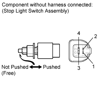
Disconnect the stop light switch assembly connector.
-
Measure the resistance according to the value(s) in the table below.
Standard Resistance Tester Connection Switch Condition Specified Condition 1 - 2 Pushed 10 kΩ or higher 3 - 4 1 - 2 Not pushed Below 1 Ω 3 - 4
NG
REPLACE STOP LIGHT SWITCH ASSEMBLY Click here
OK
-
-
CHECK HARNESS AND CONNECTOR (STOP LIGHT SWITCH ASSEMBLY - ECU)
-
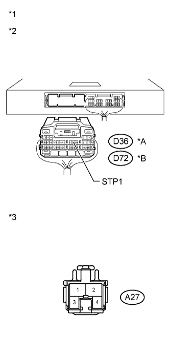
Text in Illustration *A for 1KR-FE and 1NR-FE *B for 1ND-TV *1 Rear view of wire harness connector
(to Power Management Control ECU) (for 1KR-FE and 1NR-FE)
*2 Rear view of wire harness connector
(to Power Source Control ECU) (for 1ND-TV)
*3 Component without harness connected
(Stop Light Switch Assembly)
Disconnect the D36 or D72 ECU connector.
-
Disconnect the A27 stop light switch connector.
-
Measure the resistance according to the value(s) in the table below.
-
for 1KR-FE and 1NR-FE
Standard Resistance Tester Connection Condition Specified Condition D36-11 (STP1) - A27-1 Always Below 1 Ω D36-11 (STP1) - Body ground 10 kΩ or higher
-
Reconnect the A27 stop light switch connector.
-
Measure the voltage according to the value(s) in the table below.
Standard Voltage Tester Connection Condition Specified Condition D36-11 (STP1) - Body ground Brake pedal released Below 1 V Brake pedal depressed Output voltage at terminal AM21 or AM22 -2.5 V or more
-
-
for 1ND-TV
Standard Resistance Tester Connection Condition Specified Condition D72-11 (STP1) - A27-1 Always Below 1 Ω D72-11 (STP1) - Body ground 10 kΩ or higher
-
Reconnect the A27 stop light switch connector.
-
Measure the voltage according to the value(s) in the table below.
Standard Voltage Tester Connection Condition Specified Condition D72-11 (STP1) - Body ground Brake pedal released Below 1 V Brake pedal depressed Output voltage at terminal AM21 or AM22 -2.5 V or more Result Result Proceed to OK (for 1KR-FE and 1NR-FE) A OK (for 1ND-TV) B NG C
-
B
REPLACE POWER SOURCE CONTROL ECU Click here
C
REPAIR OR REPLACE HARNESS OR CONNECTOR
A
REPLACE POWER MANAGEMENT CONTROL ECU Click here
-
-
CHECK HARNESS AND CONNECTOR (ECU - STEERING LOCK ECU)
-
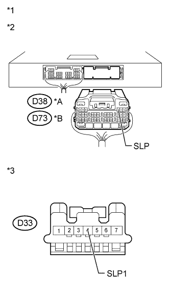
Text in Illustration *A for 1KR-FE and 1NR-FE *B for 1ND-TV *1 Rear view of wire harness connector
(to Power Management Control ECU) (for 1KR-FE and 1NR-FE)
*2 Rear view of wire harness connector
(to Power Source Control ECU) (for 1ND-TV)
*3 Front view of wire harness connector
(to Steering Lock Actuator Assembly (Steering Lock ECU))
Disconnect the D38 or D73 ECU connector.
-
Disconnect the D33 steering lock ECU connector.
-
Measure the resistance according to the value(s) in the table below.
-
for 1KR-FE and 1NR-FE
Standard Resistance Tester Connection Condition Specified Condition D38-3 (SLP) - D33-4 (SLP1) Always Below 1 Ω D38-3 (SLP) - Body ground 10 kΩ or higher -
for 1ND-TV
Standard Resistance Tester Connection Condition Specified Condition D73-3 (SLP) - D33-4 (SLP1) Always Below 1 Ω D73-3 (SLP) - Body ground 10 kΩ or higher
-
NG
REPAIR OR REPLACE HARNESS OR CONNECTOR
OK
-
-
INSPECT STEERING LOCK ACTUATOR ASSEMBLY
-
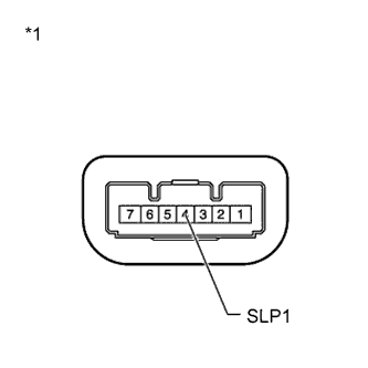
Text in Illustration *1 Component with harness connected
(Steering Lock Actuator Assembly (Steering Lock ECU))
Reconnect the D33 steering lock actuator assembly (steering lock ECU) connector.
-
Measure the resistance according to the value(s) in the table below.
Standard Resistance Tester Connection Condition Specified Condition 4 (SLP1) - Body ground Steering lock 10 kΩ or higher Steering unlock Below 1 Ω Result Result Proceed to OK (for 1KR-FE and 1NR-FE) A OK (for 1ND-TV) B NG C
B
REPLACE POWER SOURCE CONTROL ECU Click here
C
REPLACE STEERING LOCK ACTUATOR Click here
A
REPLACE POWER MANAGEMENT CONTROL ECU Click here
-
-
REPAIR OR REPLACE HARNESS OR CONNECTOR OR ST RELAY OR PARK/NEUTRAL POSITION SWITCH OR CLUTCH START SWITCH
-
Replace with a new or normally functioning part. Repair or replace any damaged wire harness or connector.
NEXT
-
-
READ VALUE USING INTELLIGENT TESTER (STARTER REQUEST SIGNAL)
-
Connect the intelligent tester to the DLC3.
-
Turn the intelligent tester on.
-
Enter the following menus: Body / Power Source Control / Data List.
-
Read the Data List according to the display on the intelligent tester.
-
Turn the engine switch on (IG).
Power Source Control Tester Display Measurement Item/Range Normal Condition Diagnostic Note Starter Request Signal Starter request signal monitor/ON or OFF ON: ST relay on
OFF: ST relay off
- Note
Check that the engine switch indicator is illuminated in green and push the engine switch.
OK Engine switch on (IG) and off appears on the screen. Result Result Proceed to OK A NG (for 1KR-FE and 1NR-FE) B NG (for 1ND-TV) C
B
REPLACE POWER MANAGEMENT CONTROL ECU Click here
C
REPLACE POWER SOURCE CONTROL ECU Click here
A
-
-
CHECK IF ENGINE STARTS
-
for Continuously Variable Transaxle: Place the electrical key on the seat. Move the shift lever to P. Step on the brake pedal.
for Manual Transaxle: Place the electrical key on the seat. Step on the clutch pedal.
-
Check that the engine switch indicator is illuminated in green, push the engine switch, and check that the engine starts.
-
Open and close the driver's door with the engine switch off.
-
Check if the engine can be started.
OK Engine can be started. Tech Tips
After the battery is discharged and then recharged or replaced, the engine may not start unless the steering lock is initialized using the above procedure.
NG
CHECK HARNESS AND CONNECTOR (BATTERY - RELAY)
OK
END
-