ENTRY AND START SYSTEM (for Start Function), Diagnostic DTC:B2286, P0335

| DTC Code | DTC Name |
|---|---|
| B2286 | Runnable Signal Malfunction |
| P0335 | Crankshaft Position Sensor "A" Circuit |
DESCRIPTION
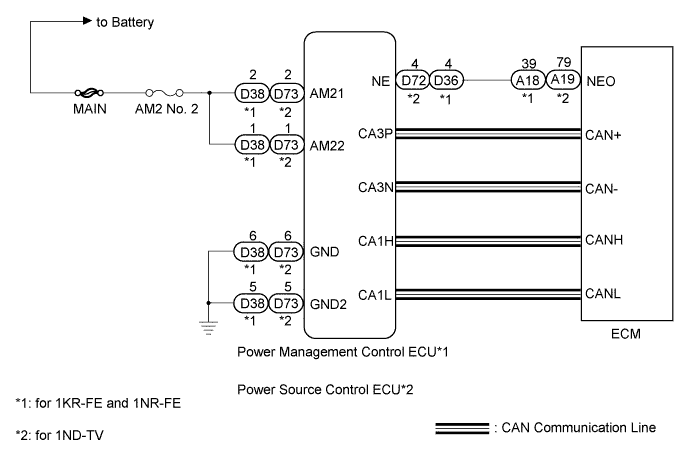
The power management control ECU*1 or power source control ECU*2 receives an engine speed signal and information that indicates whether the engine is running or not. It receives the engine speed signal from the ECM via a direct line, and the information about whether the engine is running is received from the ECM via CAN. If the information sent using these 2 methods is inconsistent, this DTC will be stored.
Tech Tips
When the power management control ECU*1 or power source control ECU*2 is replaced with a new one and the cable is connected to the negative (-) battery terminal, the power source mode becomes the IG-ON mode. When the battery is removed and reinstalled, the power source mode that was selected when the battery was removed is restored.
| DTC No. | DTC Detection Condition | Trouble Area |
|---|---|---|
| B2286 | Information received by the power management control ECU*1 or power source control ECU*2 via a direct line from the ECM and information received from the ECM via CAN is inconsistent. |
|
| DTC No. | DTC Detection Condition | Trouble Area |
|---|---|---|
| P0335 | Information received by the power management control ECU*1 or power source control ECU*2 via a direct line from the ECM and information received from the ECM via CAN is inconsistent. |
|
*1: for 1KR-FE and 1NR-FE
*2: for 1ND-TV
WIRING DIAGRAM
INSPECTION PROCEDURE
Note
Inspect the fuses for circuits related to this system before performing the following inspection procedure.
Tech Tips
Check the connector connections and terminals to make sure that there are no abnormalities such as loose connections, deformation, etc.
PROCEDURE
-
CHECK HARNESS AND CONNECTOR (POWER SOURCE)
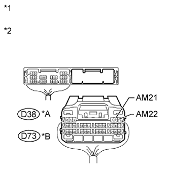
Text in Illustration *A for 1KR-FE and 1NR-FE *B for 1ND-TV *1 Rear view of wire harness connector
(to Power Management Control ECU) (for 1KR-FE and 1NR-FE)
*2 Rear view of wire harness connector
(to Power Source Control ECU) (for 1ND-TV)
-
Disconnect the D38 or D73 ECU connector.
-
Measure the voltage according to the value(s) in the table below.
-
for 1KR-FE and 1NR-FE
Standard Voltage Tester Connection Condition Specified Condition D38-2 (AM21) - Body ground Always 9.5 to 16 V D38-1 (AM22) - Body ground -
for 1ND-TV
Standard Voltage Tester Connection Condition Specified Condition D73-2 (AM21) - Body ground Always 9.5 to 16 V D73-1 (AM22) - Body ground
-
NG 
REPAIR OR REPLACE HARNESS OR CONNECTOR
OK 
-
-
CHECK HARNESS AND CONNECTOR (GROUND)
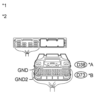
Text in Illustration *A for 1KR-FE and 1NR-FE *B for 1ND-TV *1 Rear view of wire harness connector
(to Power Management Control ECU) (for 1KR-FE and 1NR-FE)
*2 Rear view of wire harness connector
(to Power Source Control ECU) (for 1ND-TV)
-
Disconnect the D38 or D73 ECU connector.
-
Measure the resistance according to the value(s) in the table below.
-
for 1KR-FE and 1NR-FE
Standard Resistance Tester Connection Condition Specified Condition D38-6 (GND) - Body ground Always Below 1 Ω D38-5 (GND2) - Body ground -
for 1ND-TV
Standard Resistance Tester Connection Condition Specified Condition D73-6 (GND) - Body ground Always Below 1 Ω D73-5 (GND2) - Body ground
-
NG
REPAIR OR REPLACE HARNESS OR CONNECTOR
OK
-
-
CHECK HARNESS AND CONNECTOR (ECU - ECM)
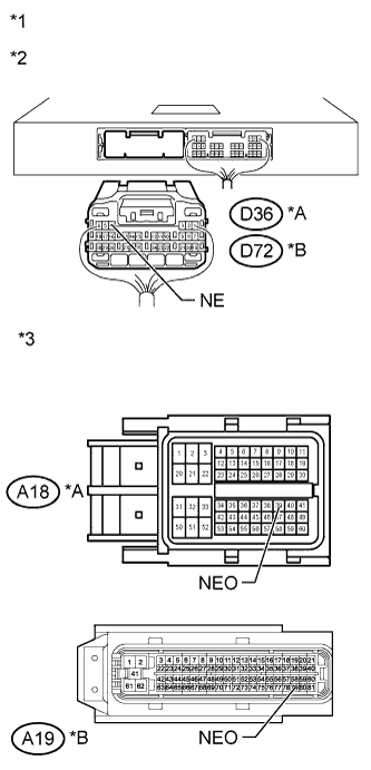
Text in Illustration *A for 1KR-FE and 1NR-FE *B for 1ND-TV *1 Rear view of wire harness connector
(to Power Management Control ECU) (for 1KR-FE and 1NR-FE)
*2 Rear view of wire harness connector
(to Power Source Control ECU) (for 1ND-TV)
*3 Front view of wire harness connector
(to ECM)
-
Replace the D36 or D72 ECU connector.
-
Replace the A18 or A19 ECM connector.
-
Measure the resistance according to the value(s) in the table below.
-
for 1KR-FE and 1NR-FE
Standard Resistance Tester Connection Condition Specified Condition D36-4 (NE) - A18-39 (NEO) Always Below 1 Ω D36-4 (NE) - Body ground 10 kΩ or higher -
for 1ND-TV
Standard Resistance Tester Connection Condition Specified Condition D72-4 (NE) - A19-79 (NEO) Always Below 1 Ω D72-4 (NE) - Body ground 10 kΩ or higher
-
NG
REPAIR OR REPLACE HARNESS OR CONNECTOR
OK
-
-
READ VALUE USING INTELLIGENT TESTER (ENGINE CONDITION)
-
Connect the intelligent tester to the DLC3.
-
Turn the engine switch on (IG).
-
Turn the intelligent tester on.
-
Enter the following menus: Body / Power Source Control / Data List.
-
Read the Data List according to the display on the intelligent tester.
Power Source Control Tester Display Measurement Item/Range Normal Condition Diagnostic Note Engine Condition Engine condition/Stop or Run Stop: Engine is stopped
Run: Engine is running
- OK Stop (engine is stopped) and Run (engine is running) appear on the screen. Result Result Proceed to OK (for 1KR-FE) A NG (for 1KR-FE and 1NR-FE) B OK (for 1NR-FE) C OK (for 1ND-TV) D NG (for 1ND-TV) E
B 
INSPECT POWER MANAGEMENT CONTROL ECU Click here
C
GO TO SFI SYSTEM Click here
D
GO TO ECD SYSTEM Click here
E
INSPECT POWER SOURCE CONTROL ECU Click here
A 
GO TO SFI SYSTEM Click here
-
-
INSPECT POWER MANAGEMENT CONTROL ECU
-
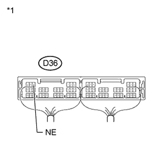
Text in Illustration *1 Rear view of wire harness connector
(to Power Management Control ECU)
Reconnect the power management control ECU connectors.
-
Connect an oscilloscope to terminal D36-4 (NE) and body ground.
-
Check the signal waveform according to the condition(s) in the table below.
OK Tester Connection Condition Specified Condition D36-4 (NE) - Body ground Engine is stopped No pulse generated Engine is running Pulse generated
(1000 rpm: 200 Hz)
Result Result Proceed to OK A NG (for 1KR-FE) B NG (for 1NR-FE) C
B
GO TO SFI SYSTEM Click here
C
GO TO SFI SYSTEM Click here
A
REPLACE POWER MANAGEMENT CONTROL ECU Click here
-
-
INSPECT POWER SOURCE CONTROL ECU
-
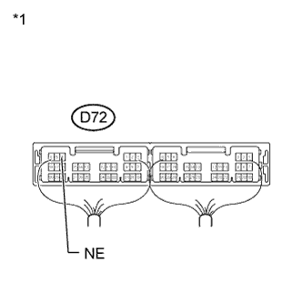
Text in Illustration *1 Rear view of wire harness connector
(to Power Source Control ECU)
Reconnect the power management control ECU connectors.
-
Connect an oscilloscope to terminal D72-4 (NE) and body ground.
-
Check the signal waveform according to the condition(s) in the table below.
OK Tester Connection Condition Specified Condition D72-4 (NE) - Body ground Engine is stopped No pulse generated Engine is running Pulse generated
(1000 rpm: 200 Hz)
NG
GO TO ECD SYSTEM Click here
OK
REPLACE POWER SOURCE CONTROL ECU Click here
-