ENTRY AND START SYSTEM (for Start Function), Diagnostic DTC:B2283

| DTC Code | DTC Name |
|---|---|
| B2283 | Vehicle Speed Sensor Malfunction |
DESCRIPTION
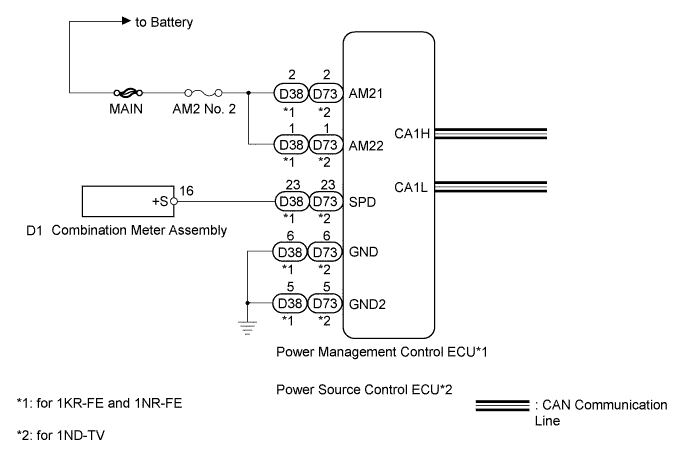
The skid control ECU converts the wheel speed sensor signals into a 4-pulse signal and sends it to the combination meter. After this signal is converted into a more precise rectangular waveform by the waveform shaping circuit inside the combination meter, it is then transmitted to the power management control ECU*1 or power source control ECU*2. The power management control ECU*1 or power source control ECU*2 determines the vehicle speed based on the frequency of this pulse signal.
Tech Tips
When the power management control ECU*1 or power source control ECU*2 is replaced with a new one and the cable is connected to the negative (-) battery terminal, the power source mode becomes the IG-ON mode. When the battery is removed and reinstalled, the power source mode that was selected when the battery was removed is restored.
| DTC No. | DTC Detection Condition | Trouble Area |
|---|---|---|
| B2283 | Both conditions below are met:
|
|
*1: for 1KR-FE and 1NR-FE
*2: for 1ND-TV
WIRING DIAGRAM
INSPECTION PROCEDURE
Note
Inspect the fuses for circuits related to this system before performing the following inspection procedure.
PROCEDURE
-
CHECK COMBINATION METER ASSEMBLY (VEHICLE SPEED METER)
-
Connect the intelligent tester to the DLC3.
-
Turn the engine switch on (IG).
-
Turn the intelligent tester on.
-
Enter the following menus: Body / Combination Meter /Data List.
-
Read the Data List according to the display on the intelligent tester.
Combination Meter Tester Display Measurement Item/Range Normal Condition Diagnostic Note Vehicle Speed Meter Vehicle speed/Min. Almost same as actual speed (When driving) - OK Vehicle speed displayed on the intelligent tester is almost the same as the actual vehicle speed measured using a speedometer tester (calibrated chassis dynamometer).
NG 
GO TO METER / GAUGE SYSTEM Click here
OK 
-
-
CHECK HARNESS AND CONNECTOR (POWER SOURCE)
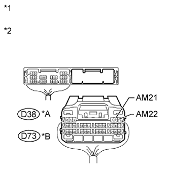
Text in Illustration *A for 1KR-FE and 1NR-FE *B for 1ND-TV *1 Rear view of wire harness connector
(to Power Management Control ECU) (for 1KR-FE and 1NR-FE)
*2 Rear view of wire harness connector
(to Power Source Control ECU) (for 1ND-TV)
-
Disconnect the D38 or D73 ECU connector.
-
Measure the voltage according to the value(s) in the table below.
-
for 1KR-FE and 1NR-FE
Standard Voltage Tester Connection Condition Specified Condition D38-2 (AM21) - Body ground Always 9.5 to 16 V D38-1 (AM22) - Body ground -
for 1ND-TV
Standard Voltage Tester Connection Condition Specified Condition D73-2 (AM21) - Body ground Always 9.5 to 16 V D73-1 (AM22) - Body ground
-
NG
REPAIR OR REPLACE HARNESS OR CONNECTOR
OK
-
-
CHECK HARNESS AND CONNECTOR (GROUND)
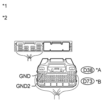
Text in Illustration *A for 1KR-FE and 1NR-FE *B for 1ND-TV *1 Rear view of wire harness connector
(to Power Management Control ECU) (for 1KR-FE and 1NR-FE)
*2 Rear view of wire harness connector
(to Power Source Control ECU) (for 1ND-TV)
-
Disconnect the D38 or D73 ECU connector.
-
Measure the resistance according to the value(s) in the table below.
-
for 1KR-FE and 1NR-FE
Standard Resistance Tester Connection Condition Specified Condition D38-6 (GND) - Body ground Always Below 1 Ω D38-5 (GND2) - Body ground -
for 1ND-TV
Standard Resistance Tester Connection Condition Specified Condition D73-6 (GND) - Body ground Always Below 1 Ω D73-5 (GND2) - Body ground
-
NG
REPAIR OR REPLACE HARNESS OR CONNECTOR
OK
-
-
CHECK HARNESS AND CONNECTOR (ECU - COMBINATION METER ASSEMBLY)
-
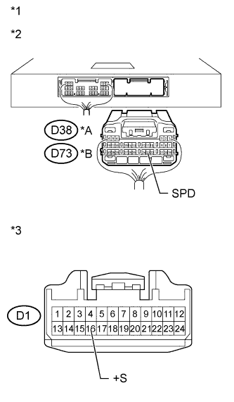
Text in Illustration *A for 1KR-FE and 1NR-FE *B for 1ND-TV *1 Rear view of wire harness connector
(to Power Management Control ECU) (for 1KR-FE and 1NR-FE)
*2 Rear view of wire harness connector
(to Power Source Control ECU) (for 1ND-TV)
*3 Front view of wire harness connector
(to Combination Meter Assembly)
Disconnect the D38 or D73 ECU connector
-
Disconnect the D1 combination meter assembly connector
-
Measure the resistance according to the value(s) in the table below.
-
for 1KR-FE and 1NR-FE
Standard Resistance Tester Connection Condition Specified Condition D1-16 (+S) - D38-23 (SPD) Always Below 1 Ω D38-23 (SPD) - Body ground Always 10 kΩ or higher -
for 1ND-TV
Standard Resistance Tester Connection Condition Specified Condition D1-16 (+S) - D73-23 (SPD) Always Below 1 Ω D73-23 (SPD) - Body ground Always 10 kΩ or higher
-
NG
REPAIR OR REPLACE HARNESS OR CONNECTOR
OK
-
-
READ VALUE USING INTELLIGENT TESTER (VEHICLE SPEED SIGNAL)
-
Connect the intelligent tester to the DLC3.
-
Turn the engine switch on (IG).
-
Turn the intelligent tester on.
-
Enter the following menus: Body / Power Source Control / Data List.
-
Read the Data List according to the display on the intelligent tester.
Power Source Control Tester Display Measurement Item/Range Normal Condition Specified Condition Vehicle speed signal Vehicle speed signal/Stop or Run Stop: Vehicle stopped
Run: Vehicle running
- OK Stop (vehicle is stopped) and Run (vehicle is running) appear on the screen. Result Result Proceed to OK A NG (for 1KR-FE and 1NR-FE) B NG (for 1ND-TV) C
B 
C
A 
GO TO METER / GAUGE SYSTEM Click here
-
-
INSPECT POWER MANAGEMENT CONTROL ECU
-

Reconnect the power management control ECU connectors.
-
Connect an oscilloscope to terminal D38-23 (SPD) and body ground.
-
Turn the engine switch on (IG).
-
Turn the wheel slowly.
Text in Illustration *1 Rear view of wire harness connector
(to Power Management Control ECU)
-
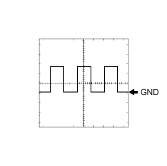
Check the signal waveform according to the condition(s) in the table below.
OK Tester Connection Tool Setting Vehicle Condition Specified Condition D38-23 (SPD) - Body ground 5 V/DIV., 20 ms./DIV. Driving at approx. 5 km/h (3 mph) Correct waveform as shown in illustration
NG
GO TO METER / GAUGE SYSTEM Click here
OK
REPLACE POWER MANAGEMENT CONTROL ECU Click here
-
-
INSPECT POWER SOURCE CONTROL ECU
-
Reconnect the power source control ECU connectors.
-
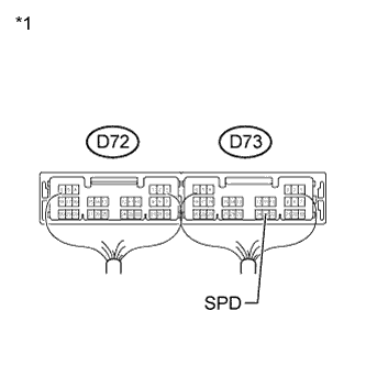
Connect an oscilloscope to terminal D73-23 (SPD) and body ground.
-
Turn the engine switch on (IG).
-
Turn the wheel slowly.
Text in Illustration *1 Rear view of wire harness connector
(to Power Source Control ECU)
-
Check the signal waveform according to the condition(s) in the table below.
OK Tester Connection Tool Setting Vehicle Condition Specified Condition D73-23 (SPD) - Body ground 5 V/DIV., 20 ms./DIV. Driving at approx. 5 km/h (3 mph) Correct waveform as shown in illustration
NG
GO TO METER / GAUGE SYSTEM Click here
OK
REPLACE POWER SOURCE CONTROL ECU Click here
-