ENTRY AND START SYSTEM (for Start Function), Diagnostic DTC:B2271

| DTC Code | DTC Name |
|---|---|
| B2271 | Ignition Hold Monitor Malfunction |
DESCRIPTION
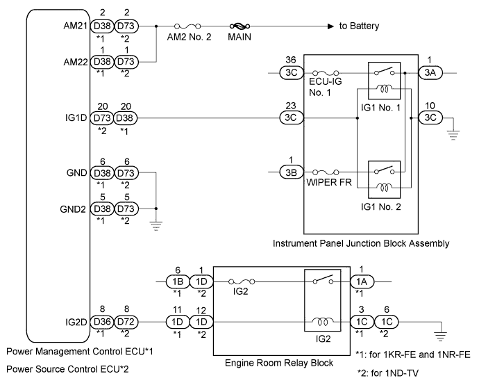
This DTC is output when a problem such as an open in the AM2 NO. 2 fuse, an open or short in the wire harness between the fuse and power management control ECU*1 or power source control ECU*2, a short in the IG output circuit inside the power management control ECU*1 or power source control ECU*2, a short between the power management control ECU*1 or power source control ECU*2 and relay, and a short in the relay is detected.
Tech Tips
When the power management control ECU*1 or power source control ECU*2 is replaced with a new one and the cable is connected to the negative (-) battery terminal, the power source mode becomes the IG-ON mode. When the battery is removed and reinstalled, the power source mode that was selected when the battery was removed is restored.
| DTC No. | DTC Detection Condition | Trouble Area |
|---|---|---|
| B2271 | The hold circuit, IG1 relay actuation circuit or IG2 relay actuation circuit inside power management control ECU*1 or power source control ECU*2 is open or short |
|
*1: for 1KR-FE and 1NR-FE
*2: for 1ND-TV
WIRING DIAGRAM
INSPECTION PROCEDURE
Note
Inspect the fuses for circuits related to this system before performing the following inspection procedure.
PROCEDURE
-
CHECK HARNESS AND CONNECTOR (POWER SOURCE)
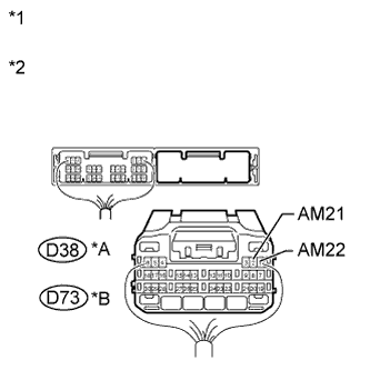
Text in Illustration *A for 1KR-FE and 1NR-FE *B for 1ND-TV *1 Rear view of wire harness connector
(to Power Management Control ECU) (for 1KR-FE and 1NR-FE)
*2 Rear view of wire harness connector
(to Power Source Control ECU) (for 1ND-TV)
-
Disconnect the D38 or D73 ECU connector.
-
Measure the voltage according to the value(s) in the table below.
-
for 1KR-FE and 1NR-FE
Standard Voltage Tester Connection Condition Specified Condition D38-2 (AM21) - Body ground Always 9.5 to 16 V D38-1 (AM22) - Body ground -
for 1ND-TV
Standard Voltage Tester Connection Condition Specified Condition D73-2 (AM21) - Body ground Always 9.5 to 16 V D73-1 (AM22) - Body ground
-
NG 
REPAIR OR REPLACE HARNESS OR CONNECTOR
OK 
-
-
CHECK HARNESS AND CONNECTOR (GROUND)
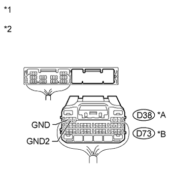
Text in Illustration *A for 1KR-FE and 1NR-FE *B for 1ND-TV *1 Rear view of wire harness connector
(to Power Management Control ECU) (for 1KR-FE and 1NR-FE)
*2 Rear view of wire harness connector
(to Power Source Control ECU) (for 1ND-TV)
-
Disconnect the D38 or D73 ECU connector.
-
Measure the resistance according to the value(s) in the table below.
-
for 1KR-FE and 1NR-FE
Standard Resistance Tester Connection Condition Specified Condition D38-6 (GND) - Body ground Always Below 1 Ω D38-5 (GND2) - Body ground -
for 1ND-TV
Standard Resistance Tester Connection Condition Specified Condition D73-6 (GND) - Body ground Always Below 1 Ω D73-5 (GND2) - Body ground
-
NG
REPAIR OR REPLACE HARNESS OR CONNECTOR
OK
-
-
INSPECT INSTRUMENT PANEL JUNCTION BLOCK ASSEMBLY AND INTEGRATION RELAY (IG1 NO. 1 RELAY, IG1 NO. 2 RELAY AND IG2 RELAY)
-
Disconnect the instrument panel junction block assembly connectors.
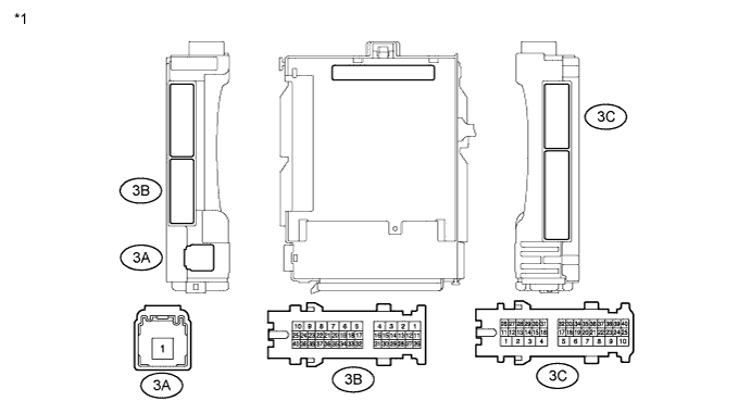
Text in Illustration *1 Component without harness connected
(Instrument Panel Junction Block Assembly)
- - -
Measure the resistance according to the value(s) in the table below.
Standard Resistance Tester Connection Condition Specified Condition 3A-1 - 3C-36 When battery voltage absent 10 kΩ or higher 3A-1 - 3B-1 3A-1 - 3C-36 When battery voltage is applied to terminals 3C-23 and 3C-10 Below 1 Ω 3A-1 - 3B-1 -
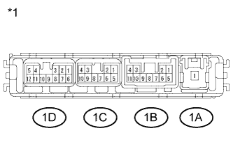
Text in Illustration *1 Component without harness connected
(Integration Relay)
Remove the integration relay from the engine room relay block.
-
Measure the resistance according to the value(s) in the table below.
-
for 1KR-FE and 1NR-FE
Standard Resistance Tester Connection Condition Specified Condition 1A-1 - 1B-6 When battery voltage absent 10 kΩ or higher When battery voltage is applied to terminals 1D-11 and 1C-3 Below 1 Ω -
for 1ND-TV
Standard Resistance Tester Connection Condition Specified Condition 1A-1 - 1D-1 When battery voltage absent 10 kΩ or higher When battery voltage is applied to terminals 1D-11 and 1C-3 Below 1 Ω
Result Result Proceed to OK A NG (for 1KR-FE and 1NR-FE) B NG (for 1ND-TV) C -
B 
REPAIR OR REPLACE HARNESS, CONNECTOR, INSTRUMENT PANEL JUNCTION BLOCK ASSEMBLY OR INTEGRATION RELAY Click here
C
REPAIR OR REPLACE HARNESS, CONNECTOR, INSTRUMENT PANEL JUNCTION BLOCK ASSEMBLY OR INTEGRATION RELAY Click here
A
-
-
CHECK HARNESS AND CONNECTOR (INSTRUMENT PANEL JUNCTION BLOCK ASSEMBLY - ECU)
-
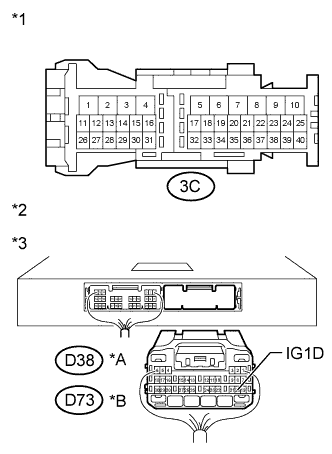
Text in Illustration *A for 1KR-FE and 1NR-FE *B for 1ND-TV *1 Front view of wire harness connector
(to Instrument Panel Junction Block Assembly)
*2 Rear view of wire harness connector
(to Power Management Control ECU) (for 1KR-FE and 1NR-FE)
*3 Rear view of wire harness connector
(to Power Source Control ECU) (for 1ND-TV)
Disconnect the instrument panel junction block assembly connectors.
-
Disconnect the D38 or D73 ECU connector.
-
Measure the resistance according to the value(s) in the table below.
-
for 1KR-FE and 1NR-FE
Standard Resistance Tester Connection Condition Specified Condition D38-20 (IG1D) - 3C-23 Always Below 1 Ω 3C-10 - Body ground -
for 1ND-TV
Standard Resistance Tester Connection Condition Specified Condition D73-20 (IG1D) - 3C-23 Always Below 1 Ω 3C-10 - Body ground Result Result Proceed to OK A NG (for 1KR-FE and 1NR-FE) B NG (for 1ND-TV) C
-
B
REPAIR OR REPLACE HARNESS, CONNECTOR, INSTRUMENT PANEL JUNCTION BLOCK ASSEMBLY OR INTEGRATION RELAY Click here
C
REPAIR OR REPLACE HARNESS, CONNECTOR, INSTRUMENT PANEL JUNCTION BLOCK ASSEMBLY OR INTEGRATION RELAY Click here
A
-
-
CHECK HARNESS AND CONNECTOR (INTEGRATION RELAY - ECU)
-
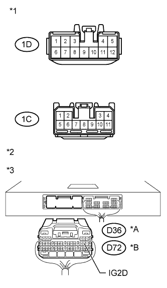
Text in Illustration *A for 1KR-FE and 1NR-FE *B for 1ND-TV *1 Front view of wire harness connector
(to Integration Relay)
*2 Rear view of wire harness connector
(to Power Management Control ECU) (for 1KR-FE and 1NR-FE)
*3 Rear view of wire harness connector
(to Power Source Control ECU) (for 1ND-TV)
Remove the integration relay from the engine room relay block.
-
Disconnect the D36 or D72 ECU connector.
-
Measure the resistance according to the value(s) in the table below.
-
for 1KR-FE and 1NR-FE
Standard Resistance Tester Connection Condition Specified Condition D36-8 (IG2D) - 1D-11 Always Below 1 Ω 1C-3 - Body ground -
for 1ND-TV
Standard Resistance Tester Connection Condition Specified Condition D72-8 (IG2D) - 1D-12 Always Below 1 Ω 1C-6 - Body ground Result Result Proceed to OK (for 1KR-FE and 1NR-FE) A OK (for 1ND-TV) B NG (for 1KR-FE and 1NR-FE) C NG (for 1ND-TV) D
-
B
INSPECT POWER SOURCE CONTROL ECU Click here
C
REPAIR OR REPLACE HARNESS, CONNECTOR, INSTRUMENT PANEL JUNCTION BLOCK ASSEMBLY OR INTEGRATION RELAY Click here
D
REPAIR OR REPLACE HARNESS, CONNECTOR, INSTRUMENT PANEL JUNCTION BLOCK ASSEMBLY OR INTEGRATION RELAY Click here
A
-
-
INSPECT POWER MANAGEMENT CONTROL ECU
-
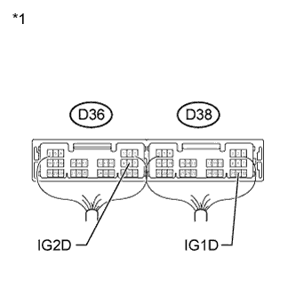
Text in Illustration *1 Rear view of wire harness connector
(to Power Management Control ECU)
Reconnect the D36 and D38 ECU connectors.
-
Measure the voltage according to the value(s) in the table below.
Standard Voltage Tester Connection Switch Condition Specified Condition D36-8 (IG2D) - Body ground Engine switch off Below 1 V Engine switch on (IG) Output voltage at terminal AM21 or AM22 is -2 V or more. D38-20 (IG1D) - Body ground Engine switch off Below 1 V Engine switch on (IG) Output voltage at terminal AM21 or AM22 is -2 V or more.
NG
REPLACE POWER MANAGEMENT CONTROL ECU Click here
OK 
END
-
-
REPAIR OR REPLACE HARNESS, CONNECTOR, INSTRUMENT PANEL JUNCTION BLOCK ASSEMBLY OR INTEGRATION RELAY
-
Replace with a new or normally functioning part. Repair or replace any damaged wire harness or connector.
NEXT
-
-
INSPECT POWER MANAGEMENT CONTROL ECU
-
Text in Illustration *1 Rear view of wire harness connector
(to Power Management Control ECU)
Reconnect the D36 and D38 ECU connectors.
-
Measure the voltage according to the value(s) in the table below.
Standard Voltage Tester Connection Switch Condition Specified Condition D36-8 (IG2D) - Body ground Engine switch off Below 1 V Engine switch on (IG) Output voltage at terminal AM21 or AM22 is -2 V or more. D38-20 (IG1D) - Body ground Engine switch off Below 1 V Engine switch on (IG) Output voltage at terminal AM21 or AM22 is -2 V or more.
NG
REPLACE POWER MANAGEMENT CONTROL ECU Click here
OK
END
-
-
INSPECT POWER SOURCE CONTROL ECU
-
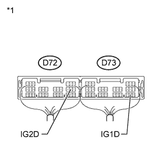
Text in Illustration *1 Rear view of wire harness connector
(to Power Source Control ECU)
Reconnect the D72 and D73 ECU connectors.
-
Measure the voltage according to the value(s) in the table below.
Standard Voltage Tester Connection Switch Condition Specified Condition D72-8 (IG2D) - Body ground Engine switch off Below 1 V Engine switch on (IG) Output voltage at terminal AM21 or AM22 is -2 V or more. D73-20 (IG1D) - Body ground Engine switch off Below 1 V Engine switch on (IG) Output voltage at terminal AM21 or AM22 is -2 V or more.
NG
REPLACE POWER SOURCE CONTROL ECU Click here
OK
END
-
-
REPAIR OR REPLACE HARNESS, CONNECTOR, INSTRUMENT PANEL JUNCTION BLOCK ASSEMBLY OR INTEGRATION RELAY
-
Replace with a new or normally functioning part. Repair or replace any damaged wire harness or connector.
NEXT
-
-
INSPECT POWER SOURCE CONTROL ECU
-
Text in Illustration *1 Rear view of wire harness connector
(to Power Source Control ECU)
Reconnect the D72 and D73 ECU connectors.
-
Measure the voltage according to the value(s) in the table below.
Standard Voltage Tester Connection Switch Condition Specified Condition D72-8 (IG2D) - Body ground Engine switch off Below 1 V Engine switch on (IG) Output voltage at terminal AM21 or AM22 is -2 V or more. D73-20 (IG1D) - Body ground Engine switch off Below 1 V Engine switch on (IG) Output voltage at terminal AM21 or AM22 is -2 V or more.
NG
REPLACE POWER SOURCE CONTROL ECU Click here
OK
END
-