ENTRY AND START SYSTEM (for Start Function) TERMINALS OF ECU

-
CHECK POWER MANAGEMENT CONTROL ECU OR POWER SOURCE CONTROL ECU
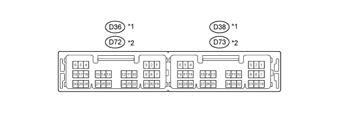
Text in Illustration *1 for 1KR-FE and 1NR-FE *2 for 1ND-TV
-
Disconnect the power management control ECU or power source control ECU connectors.
-
Measure the voltage and resistance according to the value(s) in the table below.
Tech Tips
Measure the values on the wire harness side with the connector disconnected.
Power Management Control ECU Terminal No. (Symbol) Wiring Color Terminal Description Condition Specified Condition D36-4 (NE) - Body ground P - Body ground ECM Always 10 kΩ or higher D38-1 (AM22) - Body ground L - Body ground Battery power Always 11 to 14 V D38-2 (AM21) - Body ground R - Body ground Battery power Always 11 to 14 V D38-3 (SLP) - Body ground BR - Body ground Steering lock actuator
(Steering lock ECU)
Always 10 kΩ or higher D38-5 (GND2) - Body ground W-B - Body ground Ground Always Below 1 Ω D38-6 (GND) - Body ground W-B - Body ground Ground Always Below 1 Ω D38-8 (SLR+) - Body ground GR - Body ground Steering lock actuator
(Steering lock ECU)
Always 10 kΩ or higher D38-11 (CA3N) - Body ground W - Body ground CAN line Always 10 kΩ or higher D38-12 (CA3P) - Body ground B - Body ground CAN line Always 10 kΩ or higher D38-13 (CA1L) - Body ground W - Body ground CAN line Always 10 kΩ or higher D38-14 (CA1H) - Body ground L - Body ground CAN line Always 10 kΩ or higher D38-17 (SSW2) - Body ground P - Body ground Engine switch Engine switch pushed Below 1 Ω Engine switch not pushed 10 kΩ or higher D38-18 (SSW1) - Body ground V - Body ground Engine switch Engine switch pushed Below 1 Ω Engine switch not pushed 10 kΩ or higher D38-23 (SPD) - Body ground V - Body ground Combination meter assembly Always 10 kΩ or higher D38-24 (LIN2) - Body ground P - Body ground LIN line Always 10 kΩ or higher Power Source Control ECU Terminal No. (Symbol) Wiring Color Terminal Description Condition Specified Condition D72-4 (NE) - Body ground P - Body ground ECM Always 10 kΩ or higher D73-1 (AM22) - Body ground L - Body ground Battery power Always 11 to 14 V D73-2 (AM21) - Body ground R - Body ground Battery power Always 11 to 14 V D73-3 (SLP) - Body ground BR - Body ground Steering lock actuator
(Steering lock ECU)
Always 10 kΩ or higher D73-5 (GND2) - Body ground W-B - Body ground Ground Always Below 1 Ω D73-6 (GND) - Body ground W-B - Body ground Ground Always Below 1 Ω D73-8 (SLR+) - Body ground GR - Body ground Steering lock actuator
(Steering lock ECU)
Always 10 kΩ or higher D73-11 (CA3N) - Body ground W - Body ground CAN line Always 10 kΩ or higher D73-12 (CA3P) - Body ground B - Body ground CAN line Always 10 kΩ or higher D73-13 (CA1L) - Body ground W - Body ground CAN line Always 10 kΩ or higher D73-14 (CA1H) - Body ground L - Body ground CAN line Always 10 kΩ or higher D73-17 (SSW2) - Body ground P - Body ground Engine switch Engine switch pushed Below 1 Ω Engine switch not pushed 10 kΩ or higher D73-18 (SSW1) - Body ground V - Body ground Engine switch Engine switch pushed Below 1 Ω Engine switch not pushed 10 kΩ or higher D73-23 (SPD) - Body ground V - Body ground Combination meter assembly Always 10 kΩ or higher D73-24 (LIN2) - Body ground P - Body ground LIN line Always 10 kΩ or higher If the result is not as specified, there may be a malfunction in the wire harness.
-
Reconnect the power management control ECU or power source control ECU connectors.
-
Measure the voltage according to the value(s) in the table below.
Power Management Control ECU Terminal No. (Symbol) Wiring Color Terminal Description Condition Specified Condition D36-2 (STA) - D38-6 (GND) L - W-B ST relay Cranking 6.0 V or more D36-3 (STAR) - D38-6 (GND) V - W-B ST relay Shift lever in P or N Below 1 V D36-4 (NE) - D38-6 (GND) P - W-B ECM Engine running Pulse generation D36-8 (IG2D) - D38-6 (GND) R - W-B IG2 relay Engine switch on (IG) 8 to 14 V Engine switch on (ACC) Below 1 V D36-11 (STP1) D38-6 (GND) BR - W-B Stop light switch assembly Brake pedal depressed 8 to 14 V Brake pedal released Below 1 V D38-3 (SLP) - D38-6 (GND) BR - W-B Steering lock actuator
(Steering lock ECU)
Steering lock locked 8 to 14 V Steering lock released Below 1.2 V D38-8 (SLR+) - D38-6 (GND) GR - W-B Steering lock actuator
(Steering lock ECU)
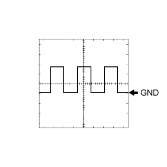
Steering lock actuator Below 1 V Steering lock actuator 8 to 14 V D38-10 (INDW) - D38-6 (GND) G - W-B Engine switch Brake pedal released, shift lever in P, engine switch on (ACC, IG) 8 to 14 V D38-16 (P)* - D38-6 (GND) R - W-B Steering lock control unit assembly Shift lever in P 8 to 14 V Shift lever not in P Below 1 V D38-17 (SSW2) - D38-6 (GND) P - W-B Engine switch Engine switch not pushed 8 to 14 V Engine switch pushed Below 1 V D38-18 (SSW1) - D38-6 (GND) V - W-B Engine switch Engine switch not pushed 8 to 14 V Engine switch pushed Below 1 V D38-19 (ACCD) - D38-6 (GND) B - W-B ACC relay Engine switch off Below 1 V Engine switch on (ACC) 8 to 14 V D38-20 (IG1D) - D38-6 (GND) LG - W-B Instrument panel junction block assembly Engine switch on (ACC) Below 1 V Engine switch on (IG) 8 to 14 V D38-22 (INDS) - D38-6 (GND) Y - W-B Engine switch Brake pedal depressed, shift lever in P 8 to 14 V D38-23 (SPD) - D38-6 (GND) V - W-B Combination meter assembly Driving at approx. 5 km/h (3 mph) Pulse generation
(See waveform 1)
*: for Continuously Variable Transaxle
Power Source Control ECU Terminal No. (Symbol) Wiring Color Terminal Description Condition Specified Condition D72-2 (STA) - D73-6 (GND) L - W-B ST relay Cranking 6.0 V or more D72-3 (STAR) - D73-6 (GND) V - W-B ST relay Shift lever in P or N Below 2 V D72-4 (NE) - D73-6 (GND) P - W-B ECM Engine running Pulse generation D72-8 (IG2D) - D73-6 (GND) R - W-B IG2 relay Engine switch on (IG) 9 to 14 V Engine switch on (ACC) Below 1 V D72-11 (STP1) D73-6 (GND) BR - W-B Stop light switch assembly Brake pedal depressed 9 to 14 V Brake pedal released Below 1 V D73-3 (SLP) - D73-6 (GND) BR - W-B Steering lock actuator
(Steering lock ECU)
Steering lock locked 11 to 14 V Steering lock released Below 1.2 V D73-8 (SLR+) - D73-6 (GND) GR - W-B Steering lock actuator
(Steering lock ECU)
Steering lock actuator Below 1 V Steering lock actuator 11 to 14 V D73-10 (INDW) - D73-6 (GND) G - W-B Engine switch Brake pedal released, shift lever in P, engine switch on (ACC, IG) 7 to 14 V D73-16 (P)* - D73-6 (GND) R - W-B Shift lock control unit assembly Shift lever in P 11 to 14 V Shift lever not in P Below 1.5 V D73-17 (SSW2) - D73-6 (GND) P - W-B Engine switch Engine switch not pushed 11 to 14 V Engine switch pushed Below 1 V D73-18 (SSW1) - D73-6 (GND) V - W-B Engine switch Engine switch not pushed 11 to 14 V Engine switch pushed Below 1 V D73-19 (ACCD) - D73-6 (GND) B - W-B ACC relay Engine switch off Below 1 V Engine switch on (ACC) 9 to 14 V D73-20 (IG1D) - D73-6 (GND) LG - W-B Instrument panel junction block assembly Engine switch on (ACC) Below 1 V Engine switch on (IG) 9 to 14 V D73-22 (INDS) - D73-6 (GND) L - W-B Engine switch Brake pedal depressed, shift lever in P 7 to 14 V D73-23 (SPD) - D73-6 (GND) V - W-B Combination meter assembly Driving at approx. 5 km/h (3 mph) Pulse generation
(See waveform 2)
*: for Continuously Variable Transaxle
Tech Tips
If the result is not as specified, the ECU may have a malfunction.
-
Using an oscilloscope, check the signal waveform of the ECU.
-
Power management control ECU
Waveform 1 (SPD) Tester Connection Tool Setting Vehicle Condition Specified Condition D38-23 (SPD) - D38-6 (GND) 5 V/DIV., 10 ms./DIV. Driving at approx. 5 km/h (3 mph) Correct waveform as shown in illustration Tech Tips
As the engine speed increases, the wavelength shortens.
-
Power source control ECU
Waveform 2 (SPD) Tester Connection Tool Setting Vehicle Condition Specified Condition D73-23 (SPD) - D73-6 (GND) 5 V/DIV., 10 ms./DIV. Driving at approx. 5 km/h (3 mph) Correct waveform as shown in illustration Tech Tips
As the engine speed increases, the wavelength shortens.
-
-
-
CHECK CERTIFICATION ECU (SMART KEY ECU ASSEMBLY)
-
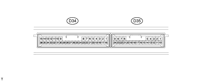
Disconnect the D34 ECU connector.
-
Measure the voltage and resistance according to the value(s) in the table below.
Tech Tips
Measure the values on the wire harness side with the connector disconnected.
Certification ECU Terminal No. (Symbol) Wiring Color Terminal Description Condition Specified Condition D34-1 (+B) - Body ground B - Body ground +B power supply Always 11 to 14 V D34-29 (LIN) - Body ground L - Body ground LIN line Always 10 kΩ or higher D34-15 (E) - Body ground W-B - Body ground Ground Always Below 1 Ω If the result is not as specified, there may be a malfunction in the wire harness.
-
-
CHECK STEERING LOCK ACTUATOR ASSEMBLY (STEERING LOCK ECU)

-
Disconnect the D33 ECU connector.
-
Measure the voltage and resistance according to the value(s) in the table below.
Steering Lock ECU Terminal No. (Symbol) Wiring Color Terminal Description Condition Specified Condition D33-1 (GND) - Body ground W-B - Body ground Ground Always Below 1 Ω D33-6 (IG2) - Body ground L - Body ground Power supply Engine switch on (IG) 11 to 14 V D33-6 (IG2) - Body ground L - Body ground Power supply Engine switch off Below 1 V D33-7 (B) - Body ground P - Body ground +B power supply Always 11 to 14 V
-
If the result is not as specified, there may be a malfunction in the wire harness.
-
-
Reconnect the D33 ECU connector.
-
Measure the voltage according to the value(s) in the table below.
Steering Lock ECU Terminal No. (Symbol) Wiring Color Terminal Description Condition Specified Condition D33-4 (SLP1) - D33-1 (GND) BR - W-B Steering lock actuator position signal Steering is locked 11 to 14 V D33-4 (SLP1) - D33-1 (GND) BR - W-B Steering lock actuator position signal Steering is released Below 1 V If the result is not as specified, the ECU may have a malfunction.
-