ENTRY AND START SYSTEM (for Start Function) SYSTEM DESCRIPTION

Tech Tips
*1: for 1KR-FE and 1NR-FE
*2: for 1ND-TV
*3: for Continuously Variable Transaxle
*4: for Manual Transaxle
-
PUSH-BUTTON START DESCRIPTION
-
The push-button start uses a push-type engine switch, which the driver can operate by merely carrying the electrical key. This system consists primarily of the power management control ECU*1 or power source control ECU*2, engine switch, ID code box (immobiliser code ECU), steering lock actuator assembly (steering lock ECU), electrical key, ACC relay, IG1 relay, IG2 relay and certification ECU (smart key ECU assembly). The power management control ECU*1 or power source control ECU*2 controls the system. This function operates in cooperation with the entry and start system.
-
-
FUNCTION OF COMPONENT
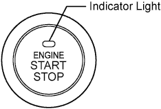
Component Function Engine Switch
-
Transponder Key Amplifier
-
Transmits an engine switch signal to the power management control ECU*1 or power source control ECU*2.
-
Informs the driver of the power source mode or a system abnormality by how the indicator light is illuminated.
-
Receives an ID code and transmits it to the certification ECU (smart key ECU assembly) when the key battery is low.
Electrical Key Receives signals from the oscillators and returns an ID code to the entry door control receiver. Electrical Key Oscillator
-
Front and Rear Floor
Receives request signals from the certification ECU (smart key ECU assembly) and forms a detection area in the vehicle interior. Door Control Receiver Receives an ID code from the electrical key and transmits it to the certification ECU (smart key ECU assembly). Power Management Control ECU*1
Power Source Control ECU*2
-
Changes power source mode in 4 stages (off, on (ACC), on (IG), start) in accordance with the shift position and state of the stop light switch assembly.
-
Controls the push-button start function in accordance with signals received from the switches and each ECU.
-
Permits the steering lock actuator assembly (steering lock ECU) to supply power to activate the motor. The power management control ECU*1 or power source control ECU*2 and certification ECU (smart key ECU assembly) permit starting of the engine after receiving an unlock signal from the steering lock actuator assembly (steering lock ECU).
Certification ECU (Smart Key ECU Assembly) Certifies the ID code received from the entry door control receiver and transmits the certification results to the ID code box (Immobiliser Code ECU) and steering lock actuator assembly (steering lock ECU). Stop Light Switch Assembly*3 Outputs the state of the brake pedal to the power management control ECU*1 or power source control ECU*2. Clutch Start Switch*4 Outputs the state of the clutch pedal to the power management control ECU*1 or power source control ECU*2. ID Code Box (Immobiliser Code ECU) Receives steering unlock or engine immobiliser unset signals from the certification ECU (smart key ECU assembly), certifies them, and transmits each unset signal to the steering lock actuator (steering lock ECU) or ECM. ECM
-
Receives an engine start request signal from the power management control ECU*1 or power source control ECU*2, turns the ST relay on, and starts the engine.
-
Receives a signal from the ID code box (immobiliser code ECU) and performs ignition and injection.
Steering Lock Actuator assembly (Steering Lock ECU) Included in the steering lock actuator assembly. Activates the steering lock motor based on permission signals from the power management control ECU*1 or power source control ECU*2 and ID code box (immobiliser code ECU).
Detects steering lock/unlock positions and transmits the status to other ECUs.
-
-
SYSTEM FUNCTION
The electric controls of the push-button start function are described below:
Control Outline Engine Switch Control
-
When the driver operates the engine switch with the electrical key in driver's possession, the certification ECU (smart key ECU assembly) starts the indoor electrical key oscillator, which transmits a request signal to the electrical key. Upon receiving this signal, the electrical key transmits an ID code signal to the power management control ECU*1 or power source control ECU*2.
-
The ID code box (immobiliser code ECU) verifies the check results received from the certification ECU (smart key ECU assembly) via LIN and sends them to the power management control ECU*1 or power source control ECU*2. Based on these results, the power management control ECU*1 or power source control ECU*2 authorizes the operation of the engine switch.
Diagnosis When the power management control ECU*1 or power source control ECU*2 detects a malfunction, the power management control ECU*1 or power source control ECU*2 diagnoses and memorizes information related to the fault. -
-
CONSTRUCTION AND OPERATION
-
Engine Switch
The engine switch consists of a momentary type switch, 2 color (amber, green) LEDs, and a transponder key amplifier.
-
The amber LED is for illumination.
-
The amber and green LEDs are for the indicator lights. The driver can check the present power source mode and whether the engine can start in accordance with the illumination state of the indicator light.
-
When the power management control ECU*1 or power source control ECU*2 detects an abnormality in the Smart Entry and Start system (for Start Function), it commands the amber indicator light to flash. If the engine is stopped in this state, it may not be possible to restart it.
-
-
Indicator Light Condition
Engine Switch Indicator Light Condition for Continuously Variable Transaxle Power Source Mode/Condition Indicator Light Condition Brake pedal released Brake pedal depressed, shift lever in P or N off off Turns on (Green) (when key and vehicle IDs match) on (ACC, IG) Turns on (Amber) Turns on (Green) Engine running off off Steering lock not unlocked Flashes (Green) for 30 sec. Flashes (Green) for 30 sec. System malfunction Flashes (Amber) for 15 sec. Flashes (Amber) for 15 sec. Engine Switch Indicator Light Condition for Manual Transaxle Power Source Mode/Condition Indicator Light Condition Clutch Pedal Released Clutch Pedal Depressed off off Turns on (Green) (when key and vehicle IDs match) on (ACC, IG) Turns on (Amber) Turns on (Green) Engine running off off Steering lock not unlocked Flashes (Green) for 30 sec. Flashes (Green) for 30 sec. System malfunction Flashes (Amber) for 15 sec. Flashes (Amber) for 15 sec. Clutch pedal switch malfunction Flashes (Green) for 30 sec. Flashes (Green) for 30 sec. -
Power management control ECU*1 or power source control ECU*2
The power management control ECU*1 or power source control ECU*2 consists of the IG1 and IG2 relay actuation circuits and CPU.
Tech Tips
Before disconnecting the cable from the negative (-) battery terminal, make sure to turn the engine switch off. The power management control ECU*1 or power source control ECU*2 constantly stores the present power source mode in its memory. Therefore, if the power management control ECU*1 or power source control ECU*2 is interrupted by disconnecting the cable, the power management control ECU*1 or power source control ECU*2 restores the power source mode after the cable is reconnected. For this reason, if the cable is disconnected when the engine switch is in a condition other than off, the power will be restored to the vehicle at the same time the power is restored to the power management control ECU*1 or power source control ECU*2 (by reconnecting the cable).
-
-
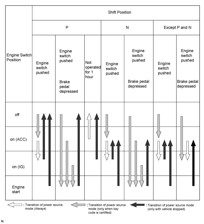
PUSH-BUTTON START FUNCTION OPERATION (for Continuously Variable Transaxle)
-
This system has different power source mode patterns depending on the brake pedal condition and shift lever position.
Brake Pedal Shift Lever Power Source Mode Pattern Depressed P or N When the engine switch is pushed once.
-
off → engine start
Not depressed P Each time the engine switch is pushed.
-
off → on (ACC) → on (IG) → off
Except P Each time the engine switch is pushed.
-
off → on (ACC) → on (IG) → on (ACC)
- P When the engine switch is pushed in the on (IG) condition (engine running).
-
on (IG) → off
- Except P When the engine switch is pushed in the on (IG) condition (engine running).
-
on (IG) → on (ACC)
When the key battery charge is low, the push-button start function can be operated by holding the key close to the engine switch.
-
After approximately 1 hour has elapsed with the engine switch on (ACC) and the shift lever in P, the power management control ECU*1 or power source control ECU*2 will automatically cut the power supply (the power source mode changes to off).
-
The illustration below shows the transition of power source modes.
Tech Tips
While the vehicle is being driven normally, operation of the engine switch is disabled. However, if the engine must be stopped in an emergency while the vehicle is being driven, pressing the engine switch for 3 seconds or more stops the engine. Power source mode changes from start to on (ACC).
-
-
-
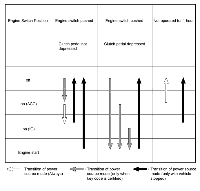
PUSH-BUTTON START FUNCTION OPERATION (for Manual Transaxle)
-
This system has different power source mode patterns depending on the clutch pedal condition.
Clutch Pedal Power Source Mode Pattern Depressed When the engine switch is pushed once.
-
off → engine start
-
on (ACC) → engine start
-
on (IG) → engine start
Not depressed Each time the engine switch is pushed.
-
off → on (ACC) → on (IG) → off
- When the engine switch is pushed in the on (IG) condition (engine running).
-
on (IG) → off
When the key battery charge is low, the push-button start function can be operated by holding the key against the engine switch.
-
After approximately 1 hour has passed with the engine switch on (ACC) and the power management control ECU*1 or power source control ECU*2 will automatically cut the power supply (the power source mode changes to off).
-
The illustration below shows the transition of power source modes.
Tech Tips
While the vehicle is being driven normally, operation of the engine switch is disabled. However, if the engine must be stopped in an emergency while the vehicle is being driven, pressing the engine switch for 3 seconds or more stops the engine. Power source mode changes from start to on (ACC).
-
-
-
WHEN KEY BATTERY IS LOW
-
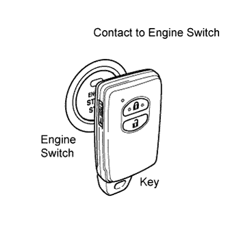
for Continuously Variable Transaxle:
To operate the push-button start function when the key battery is low, hold the key close to the engine switch with the brake pedal depressed.
for Manual Transaxle:
To operate the push-button start function when the key battery is low, hold the key close to the engine switch with the clutch pedal depressed.
-
The power management control ECU*1 or power source control ECU*2 transmits a key verification request signal from the stop light switch assembly to the certification ECU (smart key ECU assembly).
-
The certification ECU (smart key ECU assembly) does not receive an ID code response from the entry door control receiver, so it actuates the transponder key amplifier built into the engine switch.
-
The transponder key amplifier outputs an engine immobiliser radio wave to the key.
-
The key receives the radio wave, and returns a radio wave response to the transponder key amplifier.
-
The transponder key amplifier combines the key ID codes with the radio wave response, and transmits it to the certification ECU (smart key ECU assembly).
-
The certification ECU (smart key ECU assembly) judges and verifies the ID code, and transmits a key verification OK signal to the power management control ECU*1 or power source control ECU*2. The buzzer in the combination meter sounds at the same time.
-
After the buzzer sounds, if the engine switch is pressed within 5 seconds with the brake pedal not depressed, the power source mode changes to on (ACC) or on (IG), the same as in the normal condition.
-
-
DIAGNOSIS
The power management control ECU*1 or power source control ECU*2 can detect malfunctions in the push-button start function when the power source mode is on (IG).
When the ECU detects a malfunction, the amber indicator light of the engine switch flashes to warn the driver. At the same time, the ECU stores a 5-digit Diagnostic Trouble Code (DTC) in the memory.
-
The indicator light warning continues for 15 seconds even after the power source mode is changed to off.
-
The DTC can be read by connecting the intelligent tester to the DLC3.
-
The push-button start function cannot be operated if a malfunction occurs.
-