ENTRY AND START SYSTEM (for Entry Function) Back Door Entry Unlock Function does not Operate
DESCRIPTION
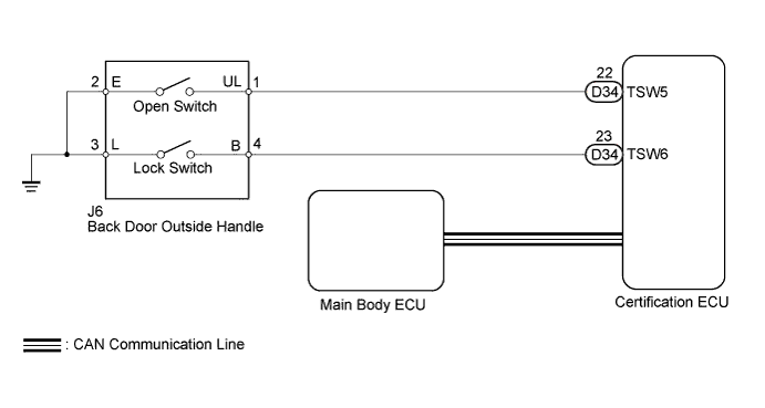
If the back door entry unlock function does not operate but the back door lock function operates, the communication between the vehicle and electrical key transmitter is normal. The malfunctioning part may be, the entry unlock switch circuit (certification ECU ← back door outside handle (unlock switch)).
WIRING DIAGRAM
INSPECTION PROCEDURE
Note
-
The entry and start system (for entry function) uses a multiplex communication system (LIN communication system) and CAN communication system. Inspect the communication function by following How to Proceed with Troubleshooting Click here. Troubleshoot the entry and start system (for entry function) after confirming that the communication system is functioning properly.
-
When using the intelligent tester with the engine switch off to troubleshoot: Connect the intelligent tester to the DLC3, and turn a courtesy light switch on and off at 1.5-second intervals until communication between the tester and vehicle begins.
PROCEDURE
-
CHECK POWER DOOR LOCK CONTROL SYSTEM
-
When the back door lock switch on the back door outside handle is operated, check that the doors lock according to switch operation Click here.
OK Door locks operate normally.
NG 
GO TO POWER DOOR LOCK CONTROL SYSTEM (PROCEED TO PROBLEM SYMPTOMS TABLE) Click here
OK 
-
-
READ VALUE USING INTELLIGENT TESTER (TR/B-DOOR UNLOCK SW)
-
Connect the intelligent tester to the DLC3.
-
Turn the engine switch on (IG).
-
Turn the intelligent tester on.
-
Enter the following menus: Body / Entry & Start / Data List.
-
Read the Data List according to the display on the intelligent tester.
Entry and Start Tester Display Measurement Item/Range Normal Condition Diagnostic Note Tr/B-Door Unlock SW Back door unlock switch / ON or OFF ON: Back door unlock switch pushed
OFF: Back door unlock switch not pushed
- OK On the intelligent tester screen, the display changes between ON and OFF as shown in the table above.
NG 
CHECK HARNESS AND CONNECTOR (BACK DOOR OPEN SWITCH - CERTIFICATION ECU AND BODY GROUND) Click here
OK 
REPLACE CERTIFICATION ECU
-
-
CHECK HARNESS AND CONNECTOR (BACK DOOR OPEN SWITCH - CERTIFICATION ECU AND BODY GROUND)
-
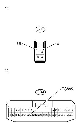
Text in Illustration *1 Front view of wire harness connector
(to Back Door Outside Handle)
*2 Front view of wire harness connector
(to Certification ECU)
Disconnect the certification ECU connector.
-
Disconnect the back door outside handle connector.
-
Measure the resistance according to the value(s) in the table below.
Standard Resistance Tester Connection Condition Specified Condition J6-1 (UL) - D34-22 (TSW5) Always Below 1 Ω J6-2 (E) - Body ground Always Below 1 Ω D34-22 (TSW5) - Body ground Always 10 kΩ or higher
NG
REPAIR OR REPLACE HARNESS OR CONNECTOR
OK
-
-
INSPECT BACK DOOR OUTSIDE HANDLE
-
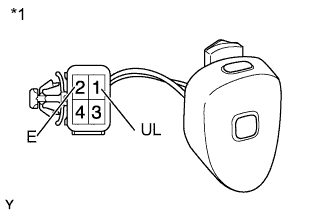
Text in Illustration *1 Component without harness connected
(Back Door Outside Handle)
Remove the back door outside handle Click here.
-
Measure the resistance according to the value(s) in the table below.
Standard Resistance Tester Connection Switch Condition Specified Condition 1 - 2 Back door open switch not pushed 10 kΩ or higher 1 - 2 Back door open switch pushed Below 1 Ω
NG
REPLACE BACK DOOR OUTSIDE HANDLE Click here
OK
REPLACE CERTIFICATION ECU
-