ENTRY AND START SYSTEM (for Entry Function) Driver Side Door Entry Lock Function does not Operate
DESCRIPTION
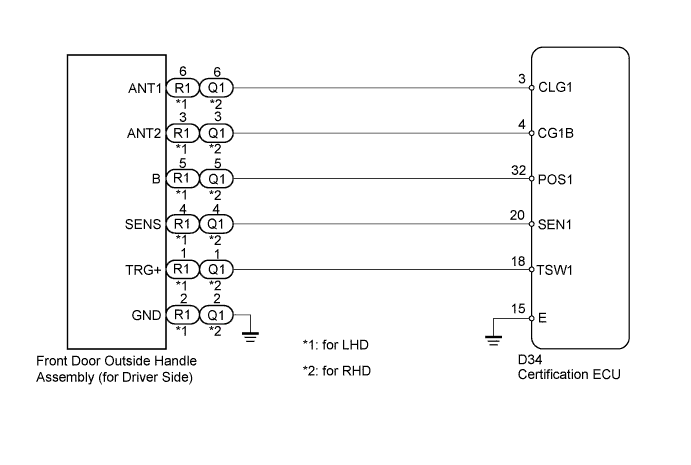
If the driver side door entry lock function does not operate but the entry unlock function operates, the communication between the vehicle and electrical key transmitter is normal. The malfunctioning part may be the lock sensor circuit (certification ECU → front door outside handle assembly (for driver side)).
WIRING DIAGRAM
INSPECTION PROCEDURE
Note
-
The entry and start system (for entry function) uses a LIN communication system and CAN communication system. Inspect the communication function by following How to Proceed with Troubleshooting Click here. Troubleshoot the entry and start system (for entry function) after confirming that the communication system is functioning properly.
-
When using the intelligent tester with the engine switch off to troubleshoot: Connect the intelligent tester to the DLC3, and turn a courtesy light switch on and off at 1.5-second intervals until communication between the tester and vehicle begins.
PROCEDURE
-
CHECK POWER DOOR LOCK OPERATION
-
When the door control switch on the master switch assembly is operated, check that the doors unlock and lock according to switch operation Click here.
OK Door locks operate normally.
NG 
GO TO POWER DOOR LOCK CONTROL SYSTEM (Proceed to Problem Symptoms Table) Click here
OK 
-
-
READ VALUE USING TECHSTREAM (DOOR LOCK POSITION SWITCH)
-
Connect the intelligent tester to the DLC3.
-
Turn the engine switch on (IG).
-
Turn the intelligent tester on.
-
Enter the following menus: Body / Main Body / Data List.
-
Read the Data List according to the display on the intelligent tester.
Main Body Tester Display Measurement Item/Range Normal Condition Diagnostic Note FL Door Lock Pos*1 Front LH door lock position switch signal / ON or OFF ON: Front LH side door unlocked
OFF: Front LH side door locked
- FR Door Lock Pos*2 Front RH door lock position switch signal / ON or OFF ON: Front RH door unlocked
OFF: Front RH side door locked
-
-
*1: for LHD
-
*2: for RHD
OK On the intelligent tester screen, the display changes between ON and OFF as shown in the chart above. Result Result Proceed to OK A NG B
(Refer to "Only Driver Door LOCK/UNLOCK Functions do not Operate" in the problem symptoms table)
-
B
GO TO POWER DOOR LOCK CONTROL SYSTEM (Proceed to Problem Symptoms Table) Click here
A
-
-
READ VALUE USING INTELLIGENT TESTER (D-DOOR TRIGGER SWITCH)
-
Connect the intelligent tester to the DLC3.
-
Turn the engine switch on (IG).
-
Turn the intelligent tester on.
-
Enter the following menus: Body / Entry & Start / Data List.
-
Read the Data List according to the display on the intelligent tester.
Entry and Start Tester Display Measurement Item/Range Normal Condition Diagnostic Note D-Door Trigger Switch Status of Trigger Switch (for driver side) / ON or OFF ON: lock sensor touched
OFF: lock sensor not touched
- OK On the intelligent tester screen, the display changes between ON and OFF as shown in the chart above.
NG 
CHECK HARNESS AND CONNECTOR (CERTIFICATION ECU - FRONT DOOR OUTSIDE HANDLE) Click here
OK 
REPLACE CERTIFICATION ECU
-
-
CHECK HARNESS AND CONNECTOR (CERTIFICATION ECU - FRONT DOOR OUTSIDE HANDLE)
-
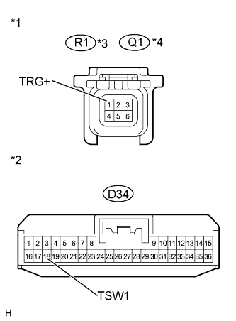
Text in Illustration *1 Front view of wire harness connector
(to Front Door Outside Handle)
*2 Front view of wire harness connector
(to Certification ECU)
*3 for LHD *4 for RHD Disconnect the certification ECU connector.
-
Disconnect the front door outside handle (for driver side) connector.
-
Measure the resistance according to the value(s) in the table below.
Standard Resistance Tester Connection Condition Specified Condition R1-1 (TRG+) - D34-18 (TSW1)*1 Always Below 1 Ω Q1-1 (TRG+) - D34-18 (TSW1)*2 Always Below 1 Ω D34-18 (TSW1) - Body ground Always 10 kΩ or higher
-
*1: for LHD
-
*2: for RHD
-
NG
REPAIR OR REPLACE HARNESS OR CONNECTOR
OK
-
-
INSPECT FRONT DOOR OUT SIDE HANDLE (FOR DRIVER SIDE)
-
Reconnect the certification ECU and front door outside handle (for driver side) connector.
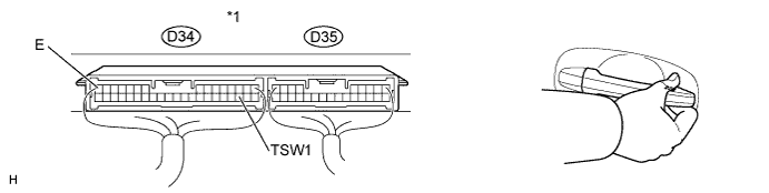
Text in Illustration *1 Component with harness connected
(Certification ECU)
-
Measure the voltage according to the value(s) in the table below.
Standard Voltage Tester Connection Condition Specified Condition D34-18 (TSW1) - D34-15 (E) Engine switch off, all doors closed, and lock sensor (driver side) off → ON Pulse generation → Below 2V
NG
REPLACE FRONT DOOR OUTSIDE HANDLE (FOR DRIVER SIDE) Click here
OK
REPLACE CERTIFICATION ECU
-