ENTRY AND START SYSTEM (for Entry Function) Front Passenger Side Door Entry Lock and Unlock Functions do not Operate
DESCRIPTION
When the front passenger door entry lock and unlock functions do not operate, any of the following may be malfunctioning: 1) power door lock control system; 2) front door outside handle assembly (for passenger side); or 3) certification ECU.
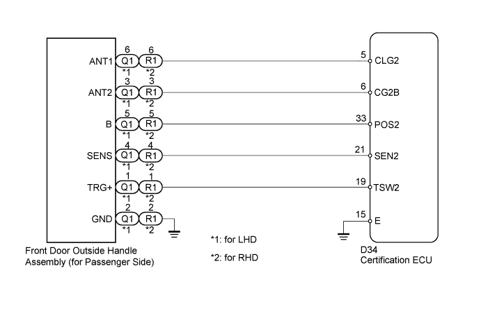
WIRING DIAGRAM
INSPECTION PROCEDURE
Note
-
The entry and start system (for entry function) uses a multiplex communication system (LIN communication system) and CAN communication system. Inspect the communication function by following How to Proceed with Troubleshooting Click here. Troubleshoot the entry and start system (for entry function) after confirming that the communication system is functioning properly.
-
When using the intelligent tester with the engine switch off to troubleshoot: Connect the intelligent tester to the DLC3, and turn a courtesy light switch on and off at 1.5-second intervals until communication between the tester and vehicle begins.
PROCEDURE
-
CHECK POWER DOOR LOCK OPERATION
-
When the door control switch on the master switch assembly is operated, check that the doors unlock and lock according to switch operation Click here.
OK Door locks operate normally.
NG 
GO TO POWER DOOR LOCK CONTROL SYSTEM (PROCEED TO PROBLEM SYMPTOMS TABLE) Click here
OK 
-
-
CHECK WAVE ENVIRONMENT
-
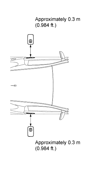
Bring the electrical key transmitter near the front door outside handle assembly (for passenger side), and perform a front passenger door entry lock and unlock operation check.
Note
If the key is brought within 0.2 m (0.656 ft.) of the door outside handle assembly, communication is not possible.
Tech Tips
-
When the electrical key transmitter is brought near the front door outside handle assembly (for passenger side), the possibility of wave interference decreases, and it can be determined if wave interference is causing the problem symptom.
-
If the operation is normal, the possibility of wave interference is high. Also, added vehicle components may cause wave interference. If installed, remove them and perform the operation check.
OK Entry functions operate normally. -
NG 
CHECK HARNESS AND CONNECTOR (CERTIFICATION ECU - DOOR OUTSIDE HANDLE ASSEMBLY) Click here
OK 
AFFECTED BY WAVE INTERFERENCE
-
-
CHECK HARNESS AND CONNECTOR (CERTIFICATION ECU - DOOR OUTSIDE HANDLE ASSEMBLY)
-
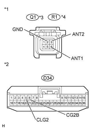
Text in Illustration *1 Front view of wire harness connector
(to Front Door Outside Handle assembly)
*2 Front view of wire harness connector
(to Certification ECU)
*3 for LHD *4 for RHD Disconnect the certification ECU connector.
-
Disconnect the front door outside handle assembly (for passenger side) connector.
-
Measure the resistance according to the value(s) in the table below.
Standard Resistance Tester Connection Condition Specified Condition Q1-3 (ANT2) - D34-6 (CG2B)*1 Always Below 1 Ω R1-3 (ANT2) - D34-6 (CG2B)*2 Always Below 1 Ω Q1-6 (ANT1) - D34-5 (CLG2)*1 Always Below 1 Ω R1-6 (ANT1) - D34-5 (CLG2)*2 Always Below 1 Ω Q1-2 (GND) - Body ground*1 Always Below 1 Ω R1-2 (GND) - Body ground*2 Always Below 1 Ω D34-6 (CG2B) - Body ground Always 10 kΩ or higher D34-5 (CLG2) - Body ground Always 10 kΩ or higher
-
*1: for LHD
-
*2: for RHD
-
NG
REPAIR OR REPLACE HARNESS OR CONNECTOR
OK
-
-
INSPECT CERTIFICATION ECU
-
Reconnect the certification ECU connector.
-
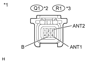
Text in Illustration *1 Front view of wire harness connector
(front door outside handle assembly)
Measure the pulse generation according to the value(s) in the table below.
OK Tester Connection Condition Specified Condition Q1-3 (ANT2) - Q1-6 (ANT1)*1 Engine switch off, all doors closed, all doors locked with wireless door lock control, and key not in the cabin No pulse generation → Pulse generation R1-3 (ANT2) - R1-6 (ANT1)*2 Engine switch off, all doors closed, all doors locked with wireless door lock control, and key not in the cabin No pulse generation → Pulse generation
-
*1: for LHD
-
*2: for RHD
-
-
Measure the voltage according to the value(s) in the table below.
Standard Voltage Tester Connection Switch Condition Specified Condition Q1-5 (B) - Body ground*1 Engine switch off →Engine switch on (IG) 9 to 12 V → Below 2 V R1-5 (B) - Body ground*2 Engine switch off →Engine switch on (IG) 9 to 12 V → Below 2 V
-
*1: for LHD
-
*2: for RHD
-
NG
REPLACE CERTIFICATION ECU
OK
-
-
REPLACE FRONT DOOR OUTSIDE HANDLE ASSEMBLY (FOR PASSENGER SIDE)
-
Replace the front door outside handle assembly (for passenger side) Click here.
NEXT
-
-
CHECK ENTRY AND START SYSTEM (OPERATION)
-
Check that the entry functions operate normally Click here.
OK Entry functions operate normally.
NG
REPLACE CERTIFICATION ECU
OK
END (DOOR OUTSIDE HANDLE ASSEMBLY IS DEFECTIVE)
-