ENGINE IMMOBILISER SYSTEM (w/ Entry and Start System) Certification ECU Power Source Circuit
DESCRIPTION
This is the power source circuit of the certification ECU.
The certification ECU controls the following:
-
Key verification confirmation
-
Indoor, outside and door oscillator control
-
Entry LOCK/UNLOCK request to the main body ECU
-
Steering LOCK/UNLOCK request
-
Immobiliser SET/UNSET request to the ID code box
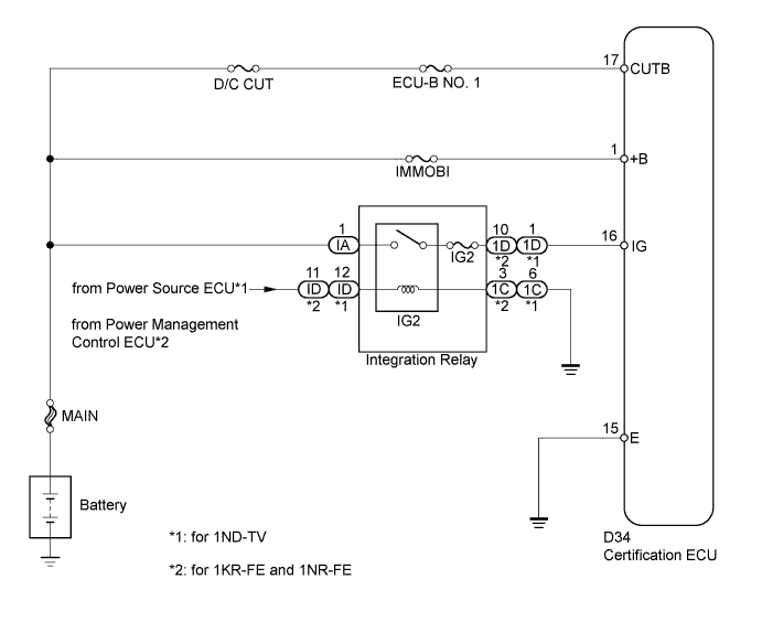
WIRING DIAGRAM
INSPECTION PROCEDURE
Note
-
If the certification ECU is replaced, register the key.
-
Inspect the fuses for circuits related to this system before performing the following inspection procedure.
PROCEDURE
-
CHECK HARNESS AND CONNECTOR (CERTIFICATION ECU - BATTERY AND BODY GROUND)
-
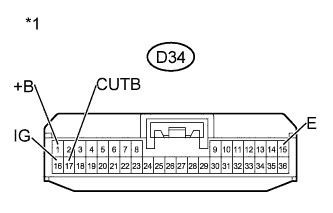
Text in Illustration *1 Front view of wire harness connector
(to Certification ECU)
Disconnect the certification ECU connector.
-
Measure the voltage according to the value(s) in the table below.
Standard Voltage Tester Connection Condition Specified Condition D34-1 (+B) - Body ground Always 11 to 14 V D34-16 (IG) - Body ground Engine switch off Below 1 V D34-16 (IG) - Body ground Engine switch on (IG) 11 to 14 V D34-17 (CUTB) - Body ground Always 11 to 14 V -
Measure the resistance according to the value(s) in the table below.
Standard Resistance Tester Connection Condition Specified Condition D34-15 (E) - Body ground Always Below 1 Ω
NG 
REPAIR OR REPLACE HARNESS OR CONNECTOR
OK 
PROCEED TO NEXT SUSPECTED AREA SHOWN IN PROBLEM SYMPTOMS TABLE Click here
-