ENGINE IMMOBILISER SYSTEM (w/ Entry and Start System), Diagnostic DTC:B278A

| DTC Code | DTC Name |
|---|---|
| B278A | Short to GND in Immobiliser System Power Source Circuit |
DESCRIPTION
This DTC is stored when the engine switch power source supply line is open or shorted.
| DTC No. | DTC Detection Condition | Trouble Area |
|---|---|---|
| B278A | Engine switch power source supply line is open or shorted. |
|
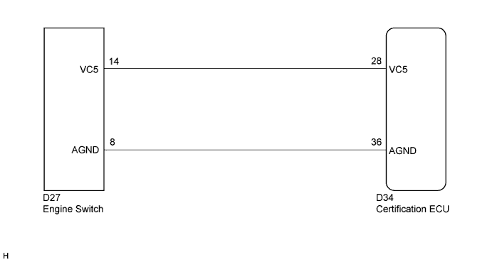
WIRING DIAGRAM
INSPECTION PROCEDURE
Note
If the certification ECU is replaced, register the key.
PROCEDURE
-
CHECK HARNESS AND CONNECTOR (CERTIFICATION ECU - ENGINE SWITCH)
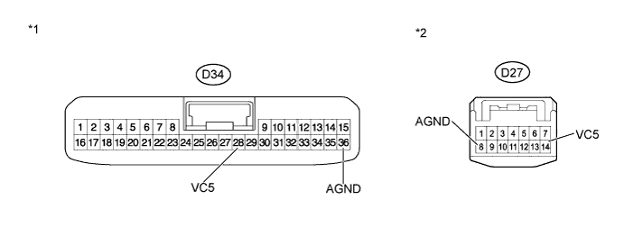
Text in Illustration *1 Front view of wire harness connector
(to Certification ECU)
*2 Front view of wire harness connector
(to Engine Switch)
-
Disconnect the certification ECU connector.
-
Disconnect the engine switch connector.
-
Measure the resistance according to the value(s) in the table below.
Standard Resistance Tester Connection Condition Specified Condition D34-28 (VC5) -D27-14 (VC5) Always Below 1 Ω D34-36 (AGND) - D27-8 (AGND) Always Below 1 Ω D34-28 (VC5) - Body ground Always 10 kΩ or higher D34-36 (AGND) - Body ground Always 10 kΩ or higher
NG 
REPAIR OR REPLACE HARNESS OR CONNECTOR
OK 
-
-
CHECK HARNESS AND CONNECTOR (ENGINE SWITCH - POWER SOURCE AND BODY GROUND)
-
Reconnect the certification ECU connector.
-
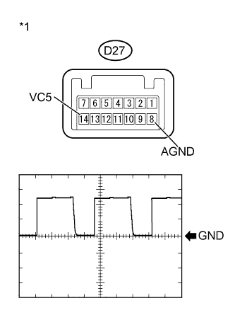
Text in Illustration *1 Component with harness connected
(Engine Switch)
Reconnect the engine switch connector.
-
Using an oscilloscope, check the waveform.
Waveform Item Content Tester Connection D27-14(VC5) - D27-8(AGND) Tool Setting 2 V/DIV - 200 ms./DIV Condition Engine switch off, key not in cabin, and 30 seconds or less after engine switch pushed. OK Waveform is output normally (see illustration)
NG
REPLACE CERTIFICATION ECU
OK 
REPLACE ENGINE SWITCH Click here
-