ENGINE IMMOBILISER SYSTEM (w/ Entry and Start System) TERMINALS OF ECU

-
CHECK ENGINE SWITCH
-
Disconnect the D27 engine switch connector.

-
Measure the resistance according to the value(s) in the table below.
Tech Tips
Measure the values on the wire harness side with the connector disconnected.
Terminal No. (Symbol) Wiring Color Terminal Description Condition Specified Condition D27-8 (AGND) - Body ground B - Body ground Ground Always Below 1 Ω If the result is not as specified, there may be a malfunction in the wire harness.
-
Reconnect the D27 engine switch connector.
-
Measure the voltage according to the value(s) in the table below.
Terminal No. (Symbol) Wiring Color Terminal Description Condition Specified Condition D27-9 (TXCT) - D27-8 (AGND) BR - B Key code output signal Engine switch off, 30 seconds or more after door opened or closed, and brake pedal or clutch pedal not depressed. Below 1 V D27-9 (TXCT) - D27-8 (AGND) BR - B Key code output signal Engine switch off, key not in cabin, and 30 seconds or less after engine switch pushed. Pulse generation
(See waveform 1)
D27-10 (CODE) - D27-8 (AGND) SB - B Demodulated signal of key code data Engine switch off, 30 seconds or more after door opened or closed, and brake pedal or clutch pedal not depressed. Below 1 V D27-10 (CODE) - D27-8 (AGND) SB - B Demodulated signal of key code data Engine switch off, and smart key brought near the engine switch and engine switch pushed*. Pulse generation
(See waveform 2)
D27-14 (VC5) - D27-8 (AGND) W - B Power supply Engine switch off, 30 seconds or more after door opened or closed, and brake pedal or clutch pedal not depressed. Below 1 V D27-14 (VC5) - D27-8 (AGND) W - B Power supply Engine switch off, key not in cabin, and 30 seconds or less after engine switch pushed. Pulse generation
(See waveform 3)
Tech Tips
*: Remove the key battery before performing this inspection.
If the result is not as specified, the engine switch may have a malfunction.
-
Inspect using an oscilloscope.
-
Waveform 1 (Reference)
Tester Connection D27-9 (TXCT) - D27-8 (AGND) Tool Setting 2 V/DIV., 20 ms./DIV. Condition Engine switch off, key not in cabin, and 30 seconds or less after engine switch pushed. -
Waveform 2
Tester Connection D27-10 (CODE) - D27-8 (AGND) Tool Setting 2 V/DIV., 20 ms./DIV. Condition Engine switch off, and smart key brought near the engine switch and engine switch pushed*. Tech Tips
*: Remove the key battery before performing this inspection.
-
Waveform 3
Tester Connection D27-14 (VC5) - D27-8 (AGND) Tool Setting 2 V/DIV., 20 ms./DIV. Condition Engine switch off, key not in cabin, and 30 seconds or less after engine switch pushed.
-
-
-
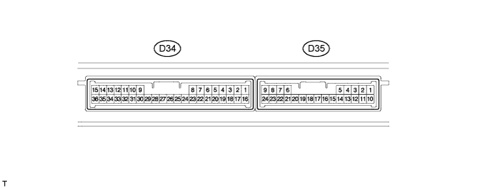
CHECK CERTIFICATION ECU
-
Disconnect the D34 certification ECU connector.
-
Measure the resistance and voltage according to the value(s) in the table below.
Tech Tips
Measure the values on the wire harness side with the connector disconnected.
Terminal No. (Symbol) Wiring Color Terminal Description Condition Specified Condition D34-1 (+B) - D34-15 (E) B - W-B +B power supply Always 11 to 14 V D34-15 (E) - Body ground W-B - Body ground Ground Always Below 1 Ω If the result is not as specified, there may be a malfunction in the wire harness.
-
Reconnect the D34 certification ECU connector.
-
Measure the resistance and voltage according to the value(s) in the table below.
Terminal No. (Symbol) Wiring Color Terminal Description Condition Specified Condition D34-12 (TXCT) - D34-36 (AGND) BR - B Engine switch TXCT output Engine switch off, 30 seconds or more after door opened or closed, and brake pedal or clutch pedal not depressed. Below 1 V D34-12 (TXCT) - D34-36 (AGND) BR - B Engine switch TXCT output Engine switch off, key not in cabin, and 30 seconds or less after engine switch pushed. Pulse generation
(See waveform 1)
D34-13 (CODE) - D34-36 (AGND) SB - B Engine switch CODE input Key not in cabin Below 1 V D34-13 (CODE) - D34-36 (AGND) SB - B Engine switch CODE input Key held close to engine switch* Pulse generation
(See waveform 2)
D34-16 (IG) - D34-15 (E) V - W-B Ignition power supply Engine switch off Below 1 V D34-16 (IG) - D34-15 (E) V - W-B Ignition power supply Engine switch on (IG) 11 to 14 V D34-28 (VC5) - D34-36 (AGND) W - B Engine switch power supply Key not in cabin Below 1 V D34-28 (VC5) - D34-36 (AGND) W - B Engine switch power supply Brake pedal depressed* Pulse generation
(See waveform 3)
D34-36 (AGND) - Body ground B - Body ground Engine switch ground Always Below 1 Ω Tech Tips
*: Remove the key battery before performing this inspection.
If the result is not as specified, the certification ECU may have a malfunction.
-
Inspect using an oscilloscope.
-

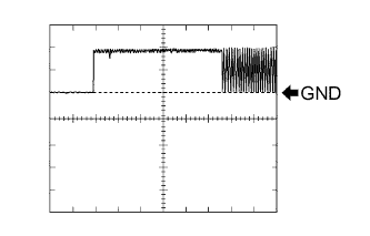
Waveform 1
Tester Connection D34-12 (TXCT) - D34-36 (AGND) Tool Setting 2 V/DIV., 20 ms./DIV. Condition Engine switch off, key not in cabin, and 30 seconds or less after engine switch pushed. -

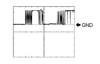
Waveform 2
Item Content Tester Connection D34-13 (CODE) - D34-36 (AGND) Tool Setting 2 V/DIV., 20 ms./DIV. Condition Engine switch off, and smart key brought near the engine switch and engine switch pushed*. Tech Tips
*: Remove the key battery before performing this inspection.
-
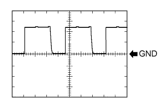
Waveform 3
Tester Connection D34-28 (VC5) - D34-36 (AGND) Tool Setting 2 V/DIV., 200 ms./DIV. Condition Engine switch off, key not in cabin, and 30 seconds or less after engine switch pushed.
-
-
-
CHECK ID CODE BOX
-
Disconnect the D30 ID code box connector.

-
Measure the resistance and voltage according to the value(s) in the table below.
Tech Tips
Measure the values on the wire harness side with the connector disconnected.
Terminal No. (Symbol) Wiring Color Terminal Description Condition Specified Condition D30-1 (+B) - D30-8 (GND) P - W-B*1
LG - W-B*2
+B power supply Always 11 to 14 V D30-8 (GND) - Body ground W-B - Body ground Ground Always Below 1 Ω
-
*1: for LHD
-
*2: for RHD
If the result is not as specified, there may be a malfunction in the wire harness.
-
-
Reconnect the D30 ID code box (immobiliser code ECU) connector.
-
Measure the voltage according to the value(s) in the table below.
Terminal No. (Symbol) Wiring Color Terminal Description Condition Specified Condition D30-5 (EFII) - D30-8 (GND) GR - W-B*1
LG - W-B*2
ECM input signal 3 seconds or less after initial combustion, or 3 seconds or less after engine switch turned on for the first time after battery reconnected. 11 to 14 V → Pulse generation
(See waveform 1)
D30-5 (EFII) - D30-8 (GND) GR - W-B*1
LG - W-B*2
ECM input signal D30-6 (EFIO) - D30-8 (GND) G - W-B*1
LG - W-B*2
ECM output signal Engine switch off → ON(IG) 11 to 14 V → Pulse generation
(See waveform 2)
D30-6 (EFIO) - D30-8 (GND) G - W-B*1
LG - W-B*2
ECM output signal
-
*1: for LHD
-
*2: for RHD
If the result is not as specified, the ID code box may have a malfunction.
-
-
Inspect using an oscilloscope.
-
Waveform 1
Tester Connection D30-5 (EFII) - D30-8 (GND) Tool Setting 2 V/DIV., 200 ms./DIV. Condition 3 seconds or less after initial combustion, or 3 seconds or less after engine switch turned on for the first time after battery reconnected. -
Waveform 2
Tester Connection D30-6 (EFIO) - D30-8 (GND) Tool Setting 10 V/DIV., 100 ms./DIV. Condition Engine switch off → on (IG)
-
-
-
CHECK STEERING LOCK ECU
-
Disconnect the D33 steering lock ECU connector.

-
Measure the resistance and voltage according to the value(s) in the table below.
Tech Tips
Measure the values on the wire harness side with the connector disconnected.
Terminal No. (Symbol) Wiring Color Terminal Description Condition Specified Condition D33-1 (GND) - Body ground W-B - Body ground Ground Always Below 1 Ω D33-6 (IG2) - Body ground L - Body ground Ignition power supply Engine switch off Below 1 V D33-6 (IG2) - Body ground L - Body ground Ignition power supply Engine switch on (IG) 11 to 14 V D33-7 (B) - Body ground P - Body ground +B power supply Always 11 to 14 V If the result is not as specified, there may be a malfunction in the wire harness.
-
-
CHECK ECM (for 1KR-FE and 1NR-FE)
-
The values listed under "Specified Condition" are reference values. Because waterproof connectors are used for ECM, inspections cannot be performed with the connectors connected.
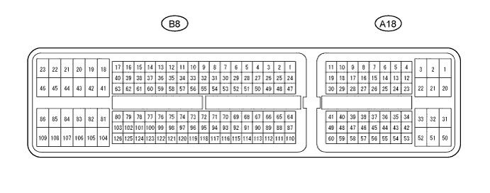
Terminal No. (Symbol) Wiring Color Terminal Description Condition Specified Condition B8-105 (E1) - Body ground BR - Body ground Ground Always Below 1 Ω A18-10 (IMO) -B8 -105 (E1) W-L - BR ID code box (immobiliser code ECU) output signal 3 seconds or less after initial combustion, or 3 seconds or less after engine switch turned on for the first time after battery reconnected. 11 to 14 V → Pulse generation
(See waveform 1)
A18-10 (IMO) - B8-105 (E1) W-L - BR ID code box (immobiliser code ECU) output signal A18-11 (IMI) - B8-105 (E1) G-B - BR ID code box (immobiliser code ECU) input signal Engine switch off → on (IG) 11 to 14 V → Pulse generation
(See waveform 2)
A18-11 (IMI) - B8-105 (E1) G-B - BR ID code box (immobiliser code ECU) input signal -
Waveform:
-
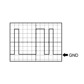
Waveform 1
Tester Connection A18-10 (IMO) - B8-105 (E1) Tool Setting 2 V/DIV., 200 ms./DIV. Condition 3 seconds or less after initial combustion, or 3 seconds or less after engine switch turned on for the first time after battery reconnected. -
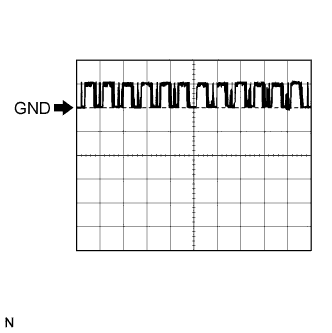
Waveform 2
Tester Connection A18-11 (IMI) - B8-105 (E1) Tool Setting 10 V/DIV., 100 ms./DIV. Condition Engine switch on (IG)
-
-
-
CHECK ECM (for 1ND-TV)
-
The values listed under "Specified Condition" are reference values. Because waterproof connectors are used for ECM, inspections can not be performed with the connectors connected.
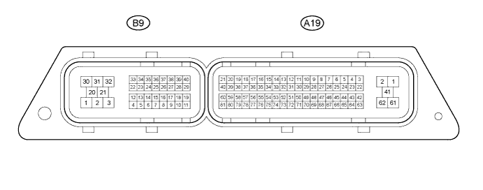
Tester Connection Wiring Color Terminal Description Condition Specified Condition A19-2 (E1) - Body ground W - B Body ground Ground Always Below 1 Ω A19-78 (IMO) - A19-2 (E1) W-L - W-B Transponder key ECU input signal Engine switch off → on (IG) 11 to 14 V → Pulse generation
(See waveform 1)
A19-77 (IMI) - A19-2 (E1) G-B - W-B Transponder key ECU output signal 3 seconds or less after initial combustion, or 3 seconds or less after engine switch turned on for the first time after battery reconnected. 11 to 14 V → Pulse generation
(See waveform 2)
-
Inspect using an oscilloscope.
-
Waveform 1
Tester Connection A19-78 (IMO) -A19-2 (E1) Tool Setting 2 V/DIV., 1 s./DIV. Condition 3 seconds or less after initial combustion, or 3 seconds or less after engine switch turned on for the first time after battery reconnected. -
Waveform 2
Tester Connection A19-77 (IMI) -A19-2 (E1) Tool Setting 2 V/DIV., 1 s./DIV. Condition Engine switch on (IG)
-
-
-
CHECK POWER SOURCE CONTROL ECU (for 1ND-TV)
-
Disconnect the D73 power source control ECU connectors.
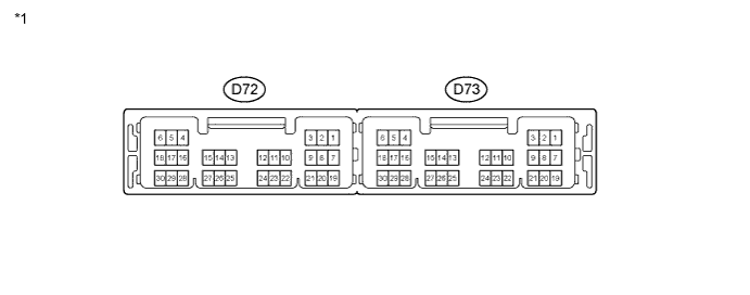
Text in Illustration *1 Power Source Control ECU -
Measure the voltage and resistance according to the value(s) in the table below.
Tech Tips
Measure the values on the wire harness side with the connector disconnected.
Terminal No. (Symbol) Wiring Color Terminal Description Condition Specified Condition D73-1 (AM22) - Body ground L - Body ground Battery power Always 11 to 14 V D73-2 (AM21) - Body ground R - Body ground Battery power Always 11 to 14 V D73-5 (GND2) - Body ground W-B - Body ground Ground Always Below 1 Ω D73-6 (GND) - Body ground W-B - Body ground Ground Always Below 1 Ω If the result is not as specified, there may be a malfunction in the wire harness.
-
-
CHECK POWER MANAGEMENT CONTROL ECU (for 1KR-FE and 1NR-FE)
-
Disconnect the D38 power management control ECU connectors.
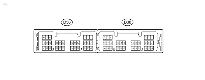
Text in Illustration *1 Power Management Control ECU -
Measure the voltage and resistance according to the value(s) in the table below.
Tech Tips
Measure the values on the wire harness side with the connector disconnected.
Terminal No. (Symbol) Wiring Color Terminal Description Condition Specified Condition D38-1 (AM22) - Body ground L - Body ground Battery power Always 11 to 14 V D38-2 (AM21) - Body ground R - Body ground Battery power Always 11 to 14 V D38-5 (GND2) - Body ground W-B - Body ground Ground Always Below 1 Ω D38-6 (GND) - Body ground W-B - Body ground Ground Always Below 1 Ω If the result is not as specified, there may be a malfunction in the wire harness.
-