UNLOCK WARNING SWITCH INSPECTION

-
INSPECT UN-LOCK WARNING SWITCH ASSEMBLY
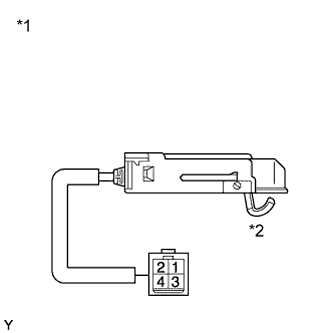
Text in Illustration *1 Component without harness connected
(Unlock Warning Switch)
*2 Lever
-
Check the resistance.
-
Measure the resistance according to the value(s) in the table below.
Standard Resistance Tester Connection Switch Condition Specified Condition 1 - 2 Lever released 10 kΩ or higher 1 - 2 Lever pushed in Below 1 Ω If the result is not as specified, replace the unlock warning switch.
-
-