ENTRY AND START SYSTEM (for Entry Function), Diagnostic DTC:B27A5

| DTC Code | DTC Name |
|---|---|
| B27A5 | Open in Front Floor Electrical Key Oscillator Circuit |
DESCRIPTION
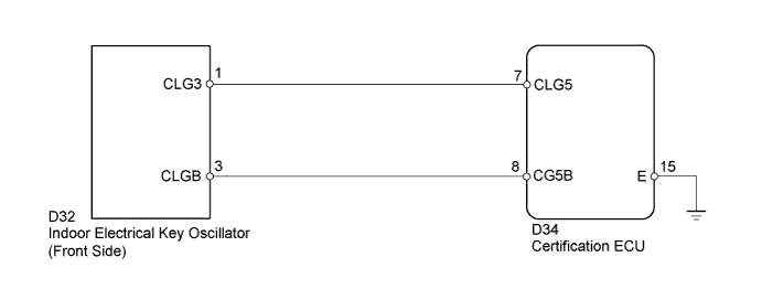
The certification ECU generates a request signal and transmits the signal to the indoor electrical key oscillator (front side). The indoor electrical key oscillator (front side) detects that the electrical key is inside the vehicle and transmits the request signal received from the certification ECU. DTC B27A5 is stored by the certification ECU when an open is detected in the terminals between the certification ECU and indoor electrical key oscillator (front side) (CLG5 - CLG3, CG5B - CLGB).
| DTC Code | DTC Detection Condition | Trouble Area |
|---|---|---|
| B27A5 | Open is detected in the terminals between the certification ECU and indoor electrical key oscillator (front side) (CLG5 - CLG3, CG5B - CLGB). |
|
WIRING DIAGRAM
INSPECTION PROCEDURE
Note
When using the intelligent tester with the engine switch off to troubleshoot: Connect the intelligent tester to the DLC3, and turn a courtesy light switch on and off at 1.5-second intervals until communication between the tester and vehicle begins
PROCEDURE
-
CHECK CONNECTOR CONNECTION CONDITION
-
Turn the engine switch off.
-
Check that the connectors are properly connected to the certification ECU and the Indoor electrical key oscillator (front side).
OK Connectors are properly connected.
NG 
CONNECT CONNECTORS PROPERLY
OK 
-
-
CHECK HARNESS AND CONNECTOR (INDOOR ELECTRICAL KEY OSCILLATOR - CERTIFICATION ECU)
-
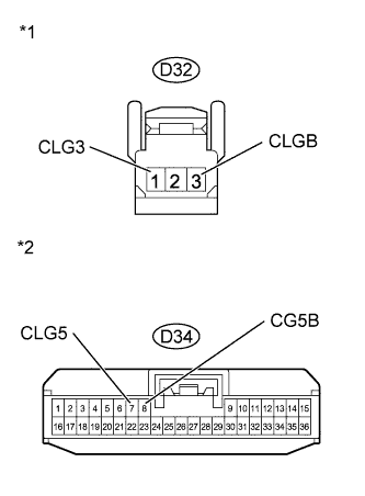
Text in Illustration *1 Front view of wire harness connector
(to Indoor Electrical Key Oscillator)
*2 Front view of wire harness connector
(to Certification ECU)
Disconnect the certification ECU connector.
-
Disconnect the indoor electrical key oscillator (front side) connector.
-
Measure the resistance according to the value(s) in the table below.
Standard Resistance Tester Connection Condition Specified Condition D32-1 (CLG3) - D34-7 (CLG5) Always Below 1 Ω D32-3 (CLGB) - D34-8 (CG5B) Always Below 1 Ω D34-7 (CLG5) - Body ground Always 10 kΩ or higher D34-8 (CG5B) - Body ground Always 10 kΩ or higher
NG
REPAIR OR REPLACE HARNESS OR CONNECTOR
OK
-
-
INSPECT CERTIFICATION ECU
-
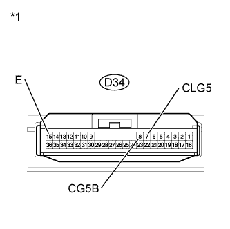
Text in Illustration *1 Component with harness connected
(Certification ECU)
Reconnect the certification ECU connector.
-
Measure the resistance according to the value(s) in the table below.
Standard Resistance Tester Connection Condition Specified Condition D34-15 (E) - Body ground Always Below 1 Ω -
Measure the pulse generation according to the value(s) in the table below.
OK Tester Connection Condition Specified Condition D34-7 (CLG5) - D34-15 (E) Engine switch off, all doors closed, key not in the cabin, and lock sensor off No pulse generation D34-7 (CLG5) - D34-15 (E) Engine switch off, all doors closed, key not in the cabin, and lock sensor ON Pulse generation D34-8 (CG5B) - D34-15 (E) Engine switch off, all doors closed, key not in the cabin, and lock sensor off No pulse generation D34-8 (CG5B) - D34-15 (E) Engine switch off, all doors closed, key not in the cabin, and lock sensor ON Pulse generation
NG
REPLACE CERTIFICATION ECU
OK
-
-
REPLACE INDOOR ELECTRICAL KEY OSCILLATOR (FRONT SIDE)
-
Temporarily replace the indoor electrical key oscillator (front side) with a new or normally functioning one Click here.
NEXT
-
-
CHECK DTC OUTPUT
-
Clear the DTCs Click here.
-
Recheck for DTCs Click here.
OK B27A5 output does not recur.
NG
REPLACE CERTIFICATION ECU
OK 
END (INDOOR ELECTRICAL KEY OSCILLATOR IS DEFECTIVE)
-