WIRELESS DOOR LOCK CONTROL SYSTEM (w/o Entry and Start System), Diagnostic DTC:B1242

| DTC Code | DTC Name |
|---|---|
| B1242 | Wireless Door Lock Tuner Circuit Malfunction |
DESCRIPTION
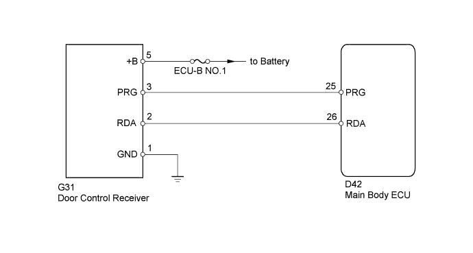
This door control receiver receives signals from the transmitter and sends these signals to the main body ECU.
| DTC No. | DTC Detection Condition | Trouble Area |
|---|---|---|
| B1242 | In diagnostic mode, applicable RDA signal cannot be received within 1 second of PRG signal being output from main body ECU. |
|
WIRING DIAGRAM
INSPECTION PROCEDURE
Note
Inspect the fuses for circuits related to this system before performing the following inspection procedure.
PROCEDURE
-
CHECK HARNESS AND CONNECTOR (MAIN BODY ECU - DOOR CONTROL RECEIVER)
-
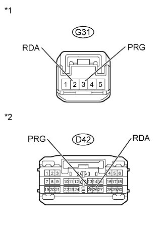
Text in Illustration *1 Front view of wire harness connector
(to Door Control Receiver)
*2 Front view of wire harness connector
(to Main Body ECU)
Disconnect the D42 main body ECU connector.
-
Disconnect the G31 door control receiver connector.
-
Measure the resistance according to the value(s) in the table below.
Standard Resistance Tester Connection Condition Specified Condition D42-26 (RDA) - G31-2 (RDA) Always Below 1 Ω D42-26 (RDA) or G31-2 (RDA) - Body ground Always 10 kΩ or higher D42-25 (PRG) - G31-3 (PRG) Always Below 1 Ω D42-25 (PRG) or G31-3 (PRG) - Body ground Always 10 kΩ or higher -
Reconnect the main body ECU connector.
-
Reconnect the door control receiver connector.
NG 
REPAIR OR REPLACE HARNESS OR CONNECTOR
OK 
-
-
INSPECT DOOR CONTROL RECEIVER (POWER SOURCE, GROUND)
-
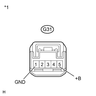
Text in Illustration *1 Front view of wire harness connector
(to Door Control Receiver)
Disconnect the G31 door control receiver connector.
-
Measure the voltage and resistance according to the value(s) in the table below.
Standard Voltage Tester Connection Condition Specified Condition G31-5 (+B) - Body ground Always 11 to 14 V Standard Resistance Tester Connection Condition Specified Condition G31-1 (GND) - Body ground Always Below 1 Ω -
Reconnect the door control receiver connector.
NG
REPAIR OR REPLACE HARNESS OR CONNECTOR
OK
-
-
REPLACE DOOR CONTROL RECEIVER
-
Temporarily replace the door control receiver with a new or normally functioning one Click here.
NEXT
-
-
REGISTER RECOGNITION CODE
-
Perform the Registration procedures Click here.
Tech Tips
If a new or normal functioning door control receiver is available, connect it and check if the wireless door lock function is normal or the DTC is output. If the alternative receiver functions normally, replace the original door control receiver.
NEXT
-
-
CLEAR DTC
-
Clear the DTC Click here.
NEXT
-
-
CHECK FOR DTC
-
Check for DTCs Click here.
OK DTC is not output. Tech Tips
Reinstall the parts, such as sensors and connectors, and restore the vehicle to its previous conditions before rechecking for DTCs.
NG
REPLACE MAIN BODY ECU Click here
OK 
END (DOOR CONTROL RECEIVER IS DEFECTIVE)
-