POWER DOOR LOCK CONTROL SYSTEM All Doors cannot be Locked / Unlocked Simultaneously
DESCRIPTION
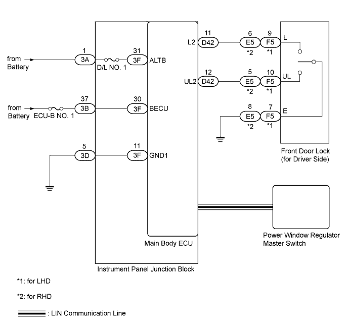
The main body ECU receives switch signals from the power window regulator master switch, and driver side door key cylinder switch signals from the front door lock. The main body ECU activates the door lock motor on each door according to these signals.
WIRING DIAGRAM
INSPECTION PROCEDURE
Note
Inspect the fuses for circuits related to this system before performing the following inspection procedure.
Tech Tips
Since the power door lock control system has functions that use LIN communication, first confirm that there is no malfunction in the communication system by inspecting the LIN communication functions in accordance with How to Proceed with Troubleshooting. Then conduct the following troubleshooting procedure.
PROCEDURE
-
CHECK DOOR LOCK OPERATION
Result Result Proceed to All doors cannot be locked through power window regulator master switch and driver side door key cylinder A All doors cannot be locked through power window regulator master switch B All doors cannot be locked through driver side door key cylinder C
B 
READ VALUE USING INTELLIGENT TESTER (DOOR LOCK SWITCH STATUS AND DOOR UNLOCK SWITCH STATUS) Click here
C
READ VALUE USING INTELLIGENT TESTER (DOOR KEY LINKED LOCK AND UNLOCK SWITCH) Click here
A 
-
CHECK HARNESS AND CONNECTOR (INSTRUMENT PANEL JUNCTION BLOCK - BATTERY AND BODY GROUND)
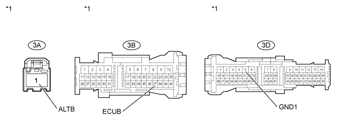
Text in Illustration *1 Front view of wire harness connector
(to Instrument Panel Junction Block)
-
Disconnect the 3A, 3B and 3D junction block connectors.
-
Measure the voltage according to the value(s) in the table below.
Standard Voltage Tester Connection Condition Specified Condition 3A-1 (ALTB) - Body ground Always 11 to 14 V 3B-37 (ECUB) - Body ground Always 11 to 14 V -
Measure the resistance according to the value(s) in the table below.
Standard Resistance Tester Connection Condition Specified Condition 3D-5 (GND1) - Body ground Always Below 1 Ω
NG 
REPAIR OR REPLACE HARNESS OR CONNECTOR
OK
-
-
REPLACE MAIN BODY ECU
-
Temporarily replace the main body ECU with a new or normally functioning one Click here.
NEXT
-
-
CHECK POWER DOOR LOCK OPERATION
-
When the door control switch on the master switch assembly is operated, check that the locked doors unlock Click here.
OK Locked doors unlock.
NG
REPLACE INSTRUMENT PANEL JUNCTION BLOCK
OK 
END (MAIN BODY ECU IS DEFECTIVE)
-
-
READ VALUE USING INTELLIGENT TESTER (DOOR LOCK SWITCH STATUS AND DOOR UNLOCK SWITCH STATUS)
-
Connect the intelligent tester to the DLC3.
-
Turn the ignition switch to ON.
-
Turn the tester on.
-
Enter the following menus: Body Electrical / Master Switch / Data List.
-
According to the display on the intelligent tester, read the Data List.
Master Switch Tester Display Measurement Item/Range Normal Condition Diagnostic Note Door Lock Switch Status Driver door lock switch signal/ ON or OFF ON: Driver door lock switch is turned to LOCK
OFF: ON: Driver door lock switch is not turned
- Door Unlock Switch Status Driver door unlock switch signal/ ON or OFF ON: Driver door unlock switch is turned to UNLOCK
OFF: ON: Driver door unlock switch is not turned
- OK The display is as specified in the normal condition column.
NG
REPLACE POWER WINDOW REGULATOR MASTER SWITCH ASSEMBLY Click here
OK
REPLACE MAIN BODY ECU Click here
-
-
READ VALUE USING INTELLIGENT TESTER (DOOR KEY LINKED LOCK AND UNLOCK SWITCH)
-
Connect the intelligent tester to the DLC3.
-
Turn the ignition switch to ON.
-
Turn the tester on.
-
Enter the following menus: Body Electrical / Main Body / Data List.
-
According to the display on the intelligent tester, read the Data List.
Main Body Tester Display Measurement Item/Range Normal Condition Diagnostic Note Door Key Linked Lock SW Door key linked lock switch signal / ON or OFF ON: Driver side door key cylinder turned to lock position
OFF: Driver side door key cylinder not turned
- Door Key Linked Unlock SW Door key linked unlock switch signal / ON or OFF ON: Driver side door key cylinder turned to unlock position
OFF: Driver side door key cylinder not turned
- OK The display is as specified in the normal condition column.
NG
CHECK HARNESS AND CONNECTOR (FRONT DOOR LOCK - MAIN BODY ECU AND BODY GROUND) Click here
OK
REPLACE MAIN BODY ECU Click here
-
-
CHECK HARNESS AND CONNECTOR (FRONT DOOR LOCK - MAIN BODY ECU AND BODY GROUND)
-
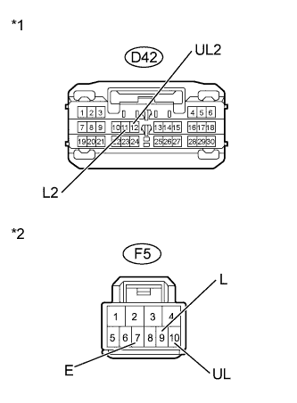
Text in Illustration *1 Front view of wire harness connector
(to Main Body ECU)
*2 Front view of wire harness connector
(to Front Door Lock)
for LHD:
-
Disconnect the F5 door lock connector.
-
Disconnect the D42 main body ECU connectors.
-
Measure the resistance according to the value(s) in the table below.
Standard Resistance Tester Connection Condition Specified Condition F5-10 (UL) - D42-12 (UL2) Always Below 1 Ω F5-9 (L) - D42-11 (L2) Always Below 1 Ω F5-7 (E) - Body ground Always Below 1 Ω F5-10 (UL) - Body ground Always 10 kΩ or higher F5-9 (L) - Body ground Always 10 kΩ or higher
-
-
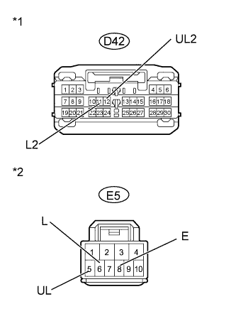
Text in Illustration *1 Front view of wire harness connector
(to Main Body ECU)
*2 Front view of wire harness connector
(to Front Door Lock)
for RHD:
-
Disconnect the E5 door lock connector.
-
Disconnect the D42 main body ECU connectors.
-
Measure the resistance according to the value(s) in the table below.
Standard Resistance Tester Connection Condition Specified Condition E5-5 (UL) - D42-12 (UL2) Always Below 1 Ω E5-6 (L) - D42-11 (L2) Always Below 1 Ω E5-8 (E) - Body ground Always Below 1 Ω E5-5 (UL) - Body ground Always 10 kΩ or higher E5-6 (L) - Body ground Always 10 kΩ or higher
-
NG
REPAIR OR REPLACE HARNESS OR CONNECTOR
OK
-
-
INSPECT FRONT DOOR LOCK ASSEMBLY (DOOR KEY LINKED LOCK AND UNLOCK SWITCH)
-
for LHD:
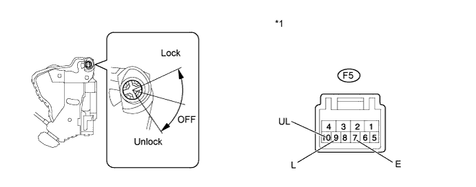
Text in Illustration *1 Component without harness connected
(Front Door Lock LH)
-
Remove the front door lock LH Click here.
-
Measure the resistance according to the value(s) in the table below.
Standard Resistance Tester Connection Condition Specified Condition 9 (L) - 7 (E) Lock Below 1 Ω 9 (L) - 7 (E) Off 10 kΩ or higher 10 (UL) - 7 (E) Unlock Below 1 Ω 10 (UL) - 7 (E) Off 10 kΩ or higher
-
-
for RHD (w/o Double Locking Function):
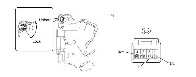
Text in Illustration *1 Component without harness connected
(Front Door Lock RH)
-
Remove the front door lock RH Click here.
-
Measure the resistance according to the value(s) in the table below.
Standard Resistance Tester Connection Condition Specified Condition 5 (UL) - 8 (E) Unlock Below 1 Ω 5 (UL) - 8 (E) Off 10 kΩ or higher 6 (L) - 8 (E) Lock Below 1 Ω 6 (L) - 8 (E) Off 10 kΩ or higher
-
-
for RHD (w/ Double Locking Function):
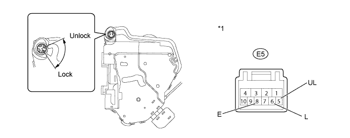
Text in Illustration *1 Component without harness connected
(Front Door Lock RH)
-
Remove the front door lock RH Click here.
-
Measure the resistance according to the value(s) in the table below.
Standard Resistance Tester Connection Condition Specified Condition 5 (UL) - 8 (E) Unlock Below 1 Ω 5 (UL) - 8 (E) Off 10 kΩ or higher 6 (L) - 8 (E) Lock Below 1 Ω 6 (L) - 8 (E) Off 10 kΩ or higher
-
NG
REPLACE FRONT DOOR LOCK Click here
OK
REPLACE MAIN BODY ECU Click here
-