CAN COMMUNICATION SYSTEM Open in One Side of CAN Branch Line
DESCRIPTION
If some ECUs and sensors are not displayed on the "Communication Bus Check" screen of the intelligent tester and some ECUs and sensors repeatedly appear and disappear on the screen when the CAN main bus wires are normal (there is no open, short, short to +B or short to GND in the main bus wires), there may be an open circuit in either of the CAN branch wires.
Tech Tips
If some ECUs and sensors repeatedly appear and disappear on the "Communication Bus Check" screen, communication between the normal ECUs and sensors and the intelligent tester may be affected by the incomplete signals that are output from the ECU that has an open circuit in either of its CAN branch wires. In this case, the CAN branch wires for the ECUs and sensors that repeatedly appear and disappear from the screen are normal and the ECU that is not displayed on the screen may be the main cause of the problem (this ECU may have an open circuit in either of its CAN branch wires).
| Symptom | Trouble Area |
|---|---|
| 2 or more ECUs and/or sensors repeatedly appear and disappear on the "Communication Bus Check" screen of the intelligent tester. | One side of a pair of CAN branch wires is open for the affected system
|
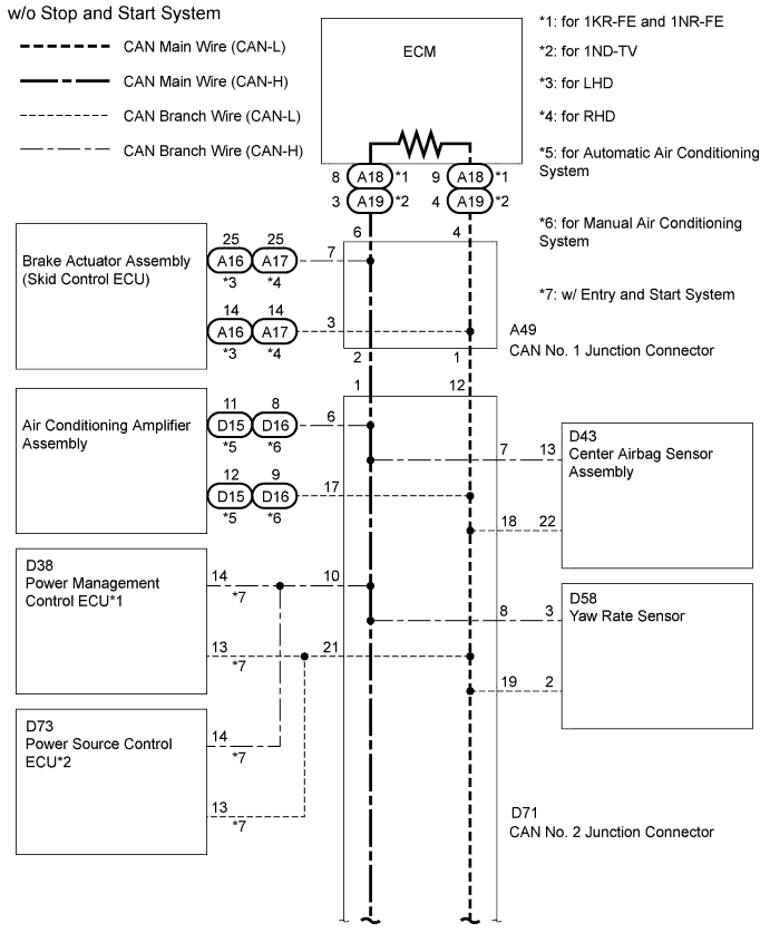
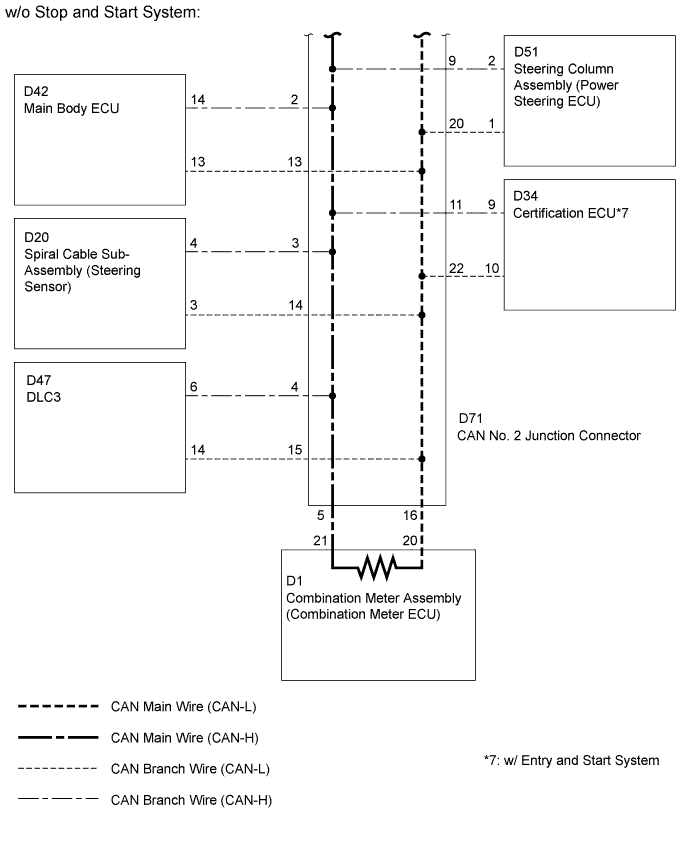
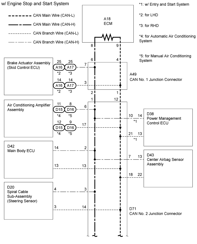
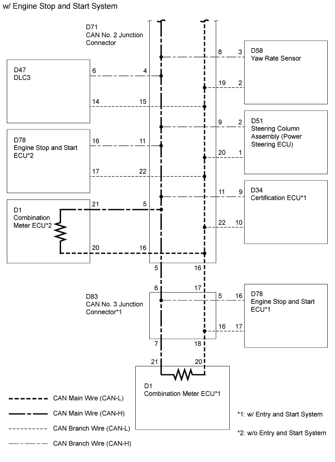
*1: w/ Entry and Start System
WIRING DIAGRAM
INSPECTION PROCEDURE
Note
-
Turn the ignition switch off before measuring the resistances of the CAN main wire and the CAN branch wire.
-
After the ignition switch is turned off, check that the key reminder warning system and light reminder warning system are not in operation.
-
Before measuring the resistance, leave the vehicle as is for at least 1 minute and do not operate the ignition switch, any other switches or the doors. If doors need to be opened in order to check connectors, open the doors and leave them open.
Tech Tips
-
Operating the ignition switch, any switches or any doors triggers related ECU and sensor communication with the CAN, which causes resistance variation.
-
Perform the following inspection for the ECUs (sensors) which are not displayed on the intelligent tester. If a malfunction cannot be identified, perform the following inspections for the ECUs (sensors) connected to the CAN communication system.
-
Do not remove the combination meter assembly (combination meter ECU) and ECM, as they are the end parts of the circuit. If removed, CAN communication will not be possible.
-
The open circuit confirmation of the combination meter assembly (combination meter ECU), ECM and main wire is performed in the CHECK CAN BUS LINE procedure of How to Proceed with Troubleshooting. This inspection only has procedures for checking for an open circuit on one side of the CAN branch wire.
PROCEDURE
-
SYSTEM CHECK
-
Check the vehicle specifications.
Result Result Proceed to w/ Stop and Start System A w/o Stop and Start System B
B 
SYSTEM CHECK Click here
A 
-
-
CHECK OPEN IN ONE SIDE OF CAN BRANCH WIRE (ENGINE STOP AND START ECU)
-
Disconnect the D78 engine stop and start ECU connector.
-
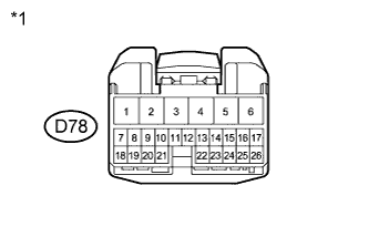
Text in Illustration *1 Front view of wire harness connector
(to Engine Stop and Start ECU)
Select "Communication Bus Check" on the intelligent tester Click here.
Result Result Proceed to Stop and Start not displayed on intelligent tester A Several ECUs and sensors other than Stop and Start not displayed on intelligent tester B
B
SYSTEM CHECK Click here
A
-
-
CHECK OPEN IN ONE SIDE OF CAN BRANCH WIRE (ENGINE STOP AND START ECU BRANCH WIRE)
-
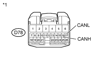
Text in Illustration *1 Front view of wire harness connector
(to Engine Stop and Start ECU)
Measure the resistance according to the value(s) in the table below.
Tech Tips
The resistance must be measured after the D78 engine stop and start ECU connector is disconnected.
Standard Resistance Tester Connection Switch Condition Specified Condition D78-16 (CANH) - D78-17 (CANL) Ignition switch off 54 to 69 Ω
NG 
REPAIR OR REPLACE CAN BRANCH WIRE OR CONNECTOR (CAN-H, CAN-L)
OK 
REPLACE ENGINE STOP AND START ECU Click here
-
-
SYSTEM CHECK
-
Check the vehicle specifications.
Result Result Proceed to w/ Entry and Start System A w/o Entry and Start System B
B
CHECK FOR OPEN IN ONE SIDE OF CAN BRANCH WIRE (SKID CONTROL ECU) Click here
A
-
-
CHECK FOR OPEN IN ONE SIDE OF CAN BRANCH WIRE (CERTIFICATION ECU)
-
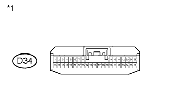
Text in Illustration *1 Front view of wire harness connector
(to Certification ECU)
Disconnect the D34 certification ECU connector.
-
Select "Communication Bus Check" on the intelligent tester Click here.
Result Result Proceed to Entry & Start / Wireless Tuner not displayed on intelligent tester A Several ECUs and sensors other than Entry & Start / Wireless Tuner not displayed on intelligent tester B
B
SYSTEM CHECK Click here
A
-
-
CHECK FOR OPEN IN ONE SIDE OF CAN BRANCH WIRE (CERTIFICATION ECU BRANCH WIRE)
-
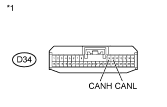
Text in Illustration *1 Front view of wire harness connector
(to Certification ECU)
Measure the resistance according to the value(s) in the table below.
Tech Tips
The resistance must be measured after the D34 certification ECU connector is disconnected.
Standard Resistance Tester Connection Switch Condition Specified Condition D34-9 (CANH) - D34-10 (CANL) Ignition switch off 54 to 69 Ω
NG
REPAIR OR REPLACE CAN BRANCH WIRE OR CONNECTOR (CAN-H, CAN-L)
OK
REPLACE CERTIFICATION ECU
-
-
SYSTEM CHECK
-
Check the vehicle specifications.
Result Result Proceed to for 1KR-FE engine and 1NR-FE engine A for 1ND-TV engine B
B
CHECK FOR OPEN IN ONE SIDE OF CAN BRANCH WIRE (POWER SOURCE CONTROL ECU) Click here
A
-
-
CHECK FOR OPEN IN ONE SIDE OF CAN BRANCH WIRE (POWER MANAGEMENT CONTROL ECU)
-

Text in Illustration *1 Front view of wire harness connector
(to Power Management Control ECU)
Disconnect the D38 power management control ECU connector.
-
Select "Communication Bus Check" on the intelligent tester Click here.
Result Result Proceed to Power Management1 not displayed on intelligent tester A Several ECUs and sensors other than Power Management1 not displayed on intelligent tester B
B
CHECK FOR OPEN IN ONE SIDE OF CAN BRANCH WIRE (SKID CONTROL ECU) Click here
A
-
-
CHECK FOR OPEN IN ONE SIDE OF CAN BRANCH WIRE (POWER MANAGEMENT CONTROL ECU BRANCH WIRE)
-
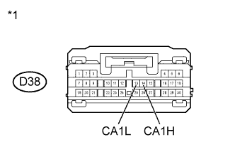
Text in Illustration *1 Front view of wire harness connector
(to Power Management Control ECU)
Measure the resistance according to the value(s) in the table below.
Tech Tips
The resistance must be measured after the D38 power management control ECU connector is disconnected.
Standard Resistance Tester Connection Switch Condition Specified Condition D38-14 (CA1H) - D38-13 (CA1L) Ignition switch off 54 to 69 Ω
NG
REPAIR OR REPLACE CAN BRANCH WIRE OR CONNECTOR (CAN-H, CAN-L)
OK
REPLACE POWER MANAGEMENT CONTROL ECU Click here
-
-
CHECK FOR OPEN IN ONE SIDE OF CAN BRANCH WIRE (POWER SOURCE CONTROL ECU)
-

Text in Illustration *1 Front view of wire harness connector
(to Power source Control ECU)
Disconnect the D73 power source control ECU connector.
-
Select "Communication Bus Check" on the intelligent tester Click here.
Result Result Proceed to Power Management1 not displayed on intelligent tester A Several ECUs and sensors other than Power Management1 not displayed on intelligent tester B
B
CHECK FOR OPEN IN ONE SIDE OF CAN BRANCH WIRE (SKID CONTROL ECU) Click here
A
-
-
CHECK FOR OPEN IN ONE SIDE OF CAN BRANCH WIRE (POWER SOURCE CONTROL ECU BRANCH WIRE)
-

Text in Illustration *1 Front view of wire harness connector
(to Power Source Control ECU)
Measure the resistance according to the value(s) in the table below.
Tech Tips
The resistance must be measured after the D73 power source control ECU connector is disconnected.
Standard Resistance Tester Connection Switch Condition Specified Condition D73-14 (CA1H) - D73-13 (CA1L) Ignition switch off 54 to 69 Ω
NG
REPAIR OR REPLACE CAN BRANCH WIRE OR CONNECTOR (CAN-H, CAN-L)
OK
REPLACE POWER SOURCE CONTROL ECU Click here
-
-
CHECK FOR OPEN IN ONE SIDE OF CAN BRANCH WIRE (SKID CONTROL ECU)
-
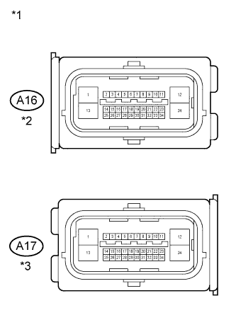
Text in Illustration *1 Front view of wire harness connector
(to Brake Actuator Assembly (Skid Control ECU))
*2 for LHD *3 for RHD Disconnect the A16 or A17 brake actuator assembly (skid control ECU) connector.
-
Select "Communication Bus Check" on the intelligent tester Click here.
Result Result Proceed to ABS/VSC/TRC not displayed on intelligent tester A Several ECUs and sensors other than ABS/VSC/TRC not displayed on intelligent tester B
B
CHECK FOR OPEN IN ONE SIDE OF CAN BRANCH WIRE (MAIN BODY ECU) Click here
A
-
-
CHECK FOR OPEN IN ONE SIDE OF CAN BRANCH WIRE (SKID CONTROL ECU BRANCH WIRE)
-
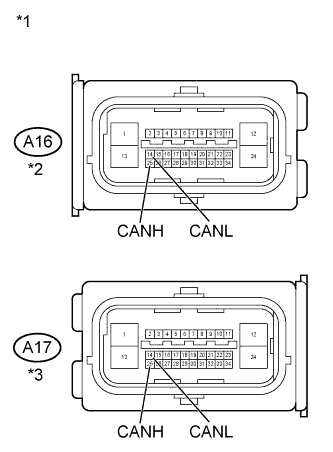
Text in Illustration *1 Front view of wire harness connector
(to Brake Actuator Assembly (Skid Control ECU))
*2 for LHD *3 for RHD Measure the resistance according to the value(s) in the table below.
Tech Tips
The resistance must be measured after the A16 or A17 brake actuator assembly (skid control ECU) connector is disconnected.
Standard Resistance for LHD Tester Connection Switch Condition Specified Condition A16-25 (CANH) - A16-14 (CANL) Ignition switch off 54 to 69 Ω for RHD Tester Connection Switch Condition Specified Condition A17-25 (CANH) - A17-14 (CANL) Ignition switch off 54 to 69 Ω
NG
REPAIR OR REPLACE CAN BRANCH WIRE OR CONNECTOR (CAN-H, CAN-L)
OK
REPLACE BRAKE ACTUATOR ASSEMBLY Click here
-
-
CHECK FOR OPEN IN ONE SIDE OF CAN BRANCH WIRE (MAIN BODY ECU)
-
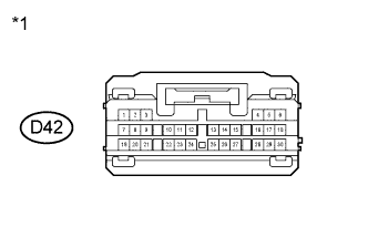
Text in Illustration *1 Front view of wire harness connector
(to Main Body ECU)
Disconnect the D42 main body ECU connector.
-
Select "Communication Bus Check" on the intelligent tester Click here.
Result Result Proceed to Main Body not displayed on intelligent tester A Several ECUs and sensors other than Main Body not displayed on intelligent tester B
B
CHECK FOR OPEN IN ONE SIDE OF CAN BRANCH WIRE (STEERING SENSOR) Click here
A
-
-
CHECK FOR OPEN IN ONE SIDE OF CAN BRANCH WIRE (MAIN BODY ECU BRANCH WIRE)
-
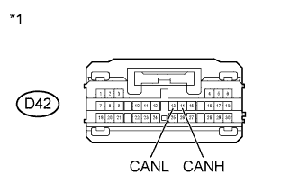
Text in Illustration *1 Front view of wire harness connector
(to Main Body ECU)
Measure the resistance according to the value(s) in the table below.
Tech Tips
The resistance must be measured after the D42 main body ECU connector is disconnected.
Standard Resistance Tester Connection Switch Condition Specified Condition D42-14 (CANH) - D42-13 (CANL) Ignition switch off 54 to 69 Ω
NG
REPAIR OR REPLACE CAN BRANCH WIRE OR CONNECTOR (CAN-H, CAN-L)
OK
REPLACE MAIN BODY ECU Click here
-
-
CHECK FOR OPEN IN ONE SIDE OF CAN BRANCH WIRE (STEERING SENSOR)
-
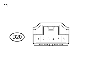
Text in Illustration *1 Front view of wire harness connector
(to Spiral Cable Sub-Assembly (Steering Sensor))
Disconnect the D20 spiral cable sub-assembly (steering sensor) connector.
-
Select "Communication Bus Check" on the intelligent tester Click here.
Result Result Proceed to Steering Angle Sensor not displayed on intelligent tester A Several ECUs and sensors other than Steering Angle Sensor not displayed on intelligent tester B
B
CHECK FOR OPEN IN ONE SIDE OF CAN BRANCH WIRE (CENTER AIRBAG SENSOR ASSEMBLY) Click here
A
-
-
CHECK FOR OPEN IN ONE SIDE OF CAN BRANCH WIRE (STEERING SENSOR BRANCH WIRE)
-
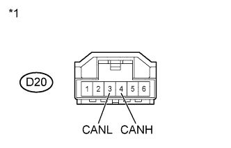
Text in Illustration *1 Front view of wire harness connector
(to Spiral Cable Sub-Assembly (Steering Sensor))
Measure the resistance according to the value(s) in the table below.
Tech Tips
The resistance must be measured after the D20 spiral cable sub-assembly (steering sensor) connector is disconnected.
Standard Resistance Tester Connection Switch Condition Specified Condition D20-4 (CANH) - D20-3 (CANL) Ignition switch off 54 to 69 Ω
NG
REPAIR OR REPLACE CAN BRANCH WIRE OR CONNECTOR (CAN-H, CAN-L)
OK
REPLACE SPIRAL CABLE SUB-ASSEMBLY Click here
-
-
CHECK FOR OPEN IN ONE SIDE OF CAN BRANCH WIRE (CENTER AIRBAG SENSOR ASSEMBLY)
-

Text in Illustration *1 Front view of wire harness connector
(to Center Airbag Sensor Assembly)
Disconnect the D43 center airbag sensor assembly connector.
-
Select "Communication Bus Check" on the intelligent tester Click here.
Result Result Proceed to SRS Airbag not displayed on intelligent tester A Several ECUs and sensors other than SRS Airbag not displayed on intelligent tester B
B
CHECK FOR OPEN IN ONE SIDE OF CAN BRANCH WIRE (YAW RATE SENSOR) Click here
A
-
-
CHECK FOR OPEN IN ONE SIDE OF CAN BRANCH WIRE (CENTER AIRBAG SENSOR ASSEMBLY BRANCH WIRE)
-
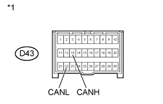
Text in Illustration *1 Front view of wire harness connector
(to Center Airbag Sensor Assembly)
Measure the resistance according to the value(s) in the table below.
Tech Tips
The resistance must be measured after the D43 center airbag sensor assembly connector is disconnected.
Standard Resistance Tester Connection Switch Condition Specified Condition D43-13 (CANH) - D43-22 (CANL) Ignition switch off 54 to 69 Ω
NG
REPAIR OR REPLACE CAN BRANCH WIRE OR CONNECTOR (CAN-H, CAN-L)
OK
REPLACE CENTER AIRBAG SENSOR ASSEMBLY Click here
-
-
CHECK FOR OPEN IN ONE SIDE OF CAN BRANCH WIRE (YAW RATE SENSOR)
-
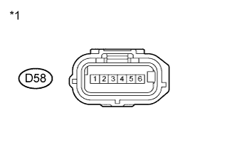
Text in Illustration *1 Front view of wire harness connector
(to Yaw Rate Sensor)
Disconnect the D58 yaw rate sensor connector.
-
Select "Communication Bus Check" on the intelligent tester Click here.
Result Result Proceed to Yaw Rate / Deceleration Sensor not displayed on intelligent tester A Several ECUs and sensors other than Yaw Rate / Deceleration Sensor not displayed on intelligent tester B
B
SYSTEM CHECK Click here
A
-
-
CHECK FOR OPEN IN ONE SIDE OF CAN BRANCH WIRE (YAW RATE SENSOR BRANCH WIRE)
-
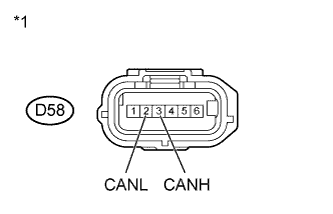
Text in Illustration *1 Front view of wire harness connector
(to Yaw Rate Sensor)
Measure the resistance according to the value(s) in the table below.
Tech Tips
The resistance must be measured after the D58 yaw rate sensor connector is disconnected.
Standard Resistance Tester Connection Switch Condition Specified Condition D58-3 (CANH) - D58-2 (CANL) Ignition switch off 54 to 69 Ω
NG
REPAIR OR REPLACE CAN BRANCH WIRE OR CONNECTOR (CAN-H, CAN-L)
OK
REPLACE YAW RATE SENSOR Click here
-
-
SYSTEM CHECK
-
Check the vehicle specifications.
Result Result Proceed to for automatic air conditioning system A for manual air conditioning system B
B
CHECK FOR OPEN IN ONE SIDE OF CAN BRANCH WIRE (AIR CONDITIONING AMPLIFIER ASSEMBLY) Click here
A
-
-
CHECK FOR OPEN IN ONE SIDE OF CAN BRANCH WIRE (AIR CONDITIONING AMPLIFIER ASSEMBLY)
-
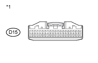
Text in Illustration *1 Front view of wire harness connector
(to Air Conditioning Amplifier Assembly)
Disconnect the D15 air conditioning amplifier assembly connector.
-
Select "Communication Bus Check" on the intelligent tester Click here.
Result Result Proceed to Air Conditioner not displayed on intelligent tester A Several ECUs and sensors other than Air Conditioner not displayed on intelligent tester B
B
CHECK FOR OPEN IN ONE SIDE OF CAN BRANCH WIRE (POWER STEERING ECU BRANCH WIRE) Click here
A
-
-
CHECK FOR OPEN IN ONE SIDE OF CAN BRANCH WIRE (AIR CONDITIONING AMPLIFIER ASSEMBLY BRANCH WIRE)
-
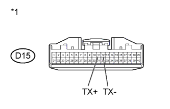
Text in Illustration *1 Front view of wire harness connector
(to Air Conditioning Amplifier Assembly)
Measure the resistance according to the value(s) in the table below.
Tech Tips
The resistance must be measured after the D15 air conditioning amplifier assembly connector is disconnected.
Standard Resistance Tester Connection Switch Condition Specified Condition D15-11 (TX+) - D15-12 (TX-) Ignition switch off 54 to 69 Ω
NG
REPAIR OR REPLACE CAN BRANCH WIRE OR CONNECTOR (CAN-H, CAN-L)
OK
REPLACE AIR CONDITIONING AMPLIFIER ASSEMBLY Click here
-
-
CHECK FOR OPEN IN ONE SIDE OF CAN BRANCH WIRE (AIR CONDITIONING AMPLIFIER ASSEMBLY)
-
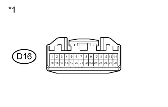
Text in Illustration *1 Front view of wire harness connector
(to Air Conditioning Amplifier Assembly)
Disconnect the D16 air conditioning amplifier assembly connector.
-
Select "Communication Bus Check" on the intelligent tester Click here.
Result Result Proceed to Air Conditioner not displayed on intelligent tester A Several ECUs and sensors other than Air Conditioner not displayed on intelligent tester B
B
CHECK FOR OPEN IN ONE SIDE OF CAN BRANCH WIRE (POWER STEERING ECU BRANCH WIRE) Click here
A
-
-
CHECK FOR OPEN IN ONE SIDE OF CAN BRANCH WIRE (AIR CONDITIONING AMPLIFIER ASSEMBLY BRANCH WIRE)
-
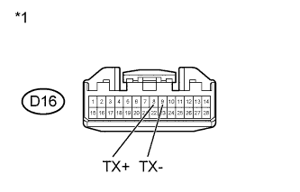
Text in Illustration *1 Front view of wire harness connector
(to Air Conditioning Amplifier Assembly)
Measure the resistance according to the value(s) in the table below.
Tech Tips
The resistance must be measured after the D16 air conditioning amplifier assembly connector is disconnected.
Standard Resistance Tester Connection Switch Condition Specified Condition D16-8 (TX+) - D16-9 (TX-) Ignition switch off 54 to 69 Ω
NG
REPAIR OR REPLACE CAN BRANCH WIRE OR CONNECTOR (CAN-H, CAN-L)
OK
REPLACE AIR CONDITIONING AMPLIFIER ASSEMBLY Click here
-
-
CHECK FOR OPEN IN ONE SIDE OF CAN BRANCH WIRE (POWER STEERING ECU BRANCH WIRE)
-
Disconnect the D51 steering column assembly (power steering ECU) connector.
-
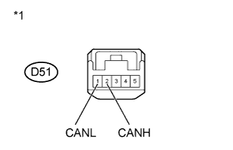
Text in Illustration *1 Front view of wire harness connector
(to Steering Column Assembly (Power Steering ECU))
Measure the resistance according to the value(s) in the table below.
Standard Resistance Tester Connection Switch Condition Specified Condition D51-2 (CANH) - D51-1 (CANL) Ignition switch off 54 to 69 Ω
NG
REPAIR OR REPLACE CAN BRANCH WIRE OR CONNECTOR (CAN-H, CAN-L)
OK
REPLACE STEERING COLUMN ASSEMBLY Click here
-