CAN COMMUNICATION SYSTEM Check CAN Bus Line
DESCRIPTION
When any DTC for the CAN communication system is output, first measure the resistance between the terminals of the DLC3 to determine the trouble area, and check that there is no short in the CAN main wire, between the CAN bus lines, to +B, or to GND.
WIRING DIAGRAM
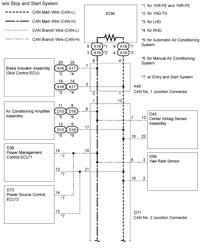
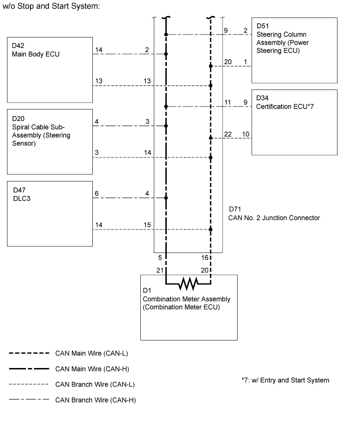
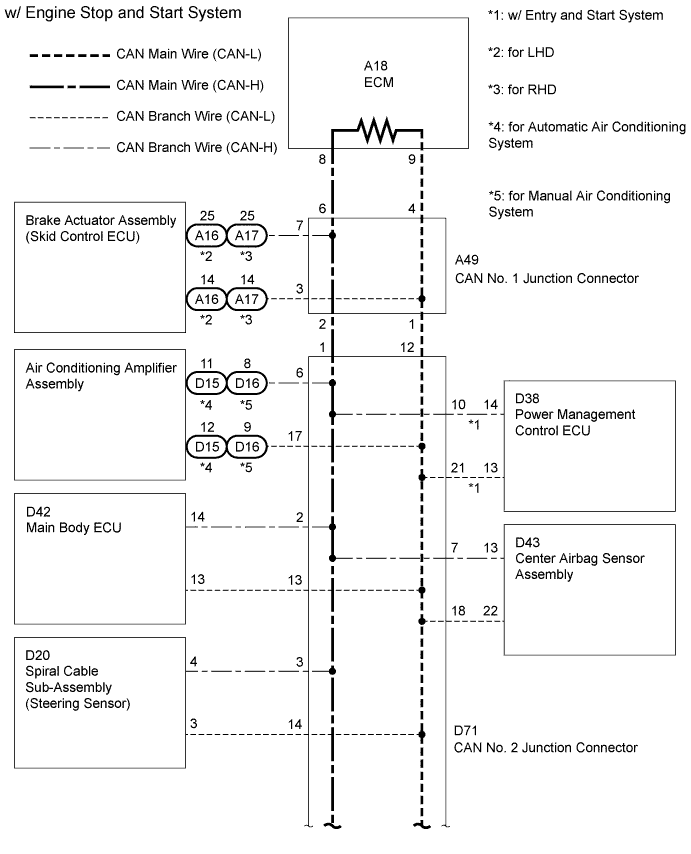
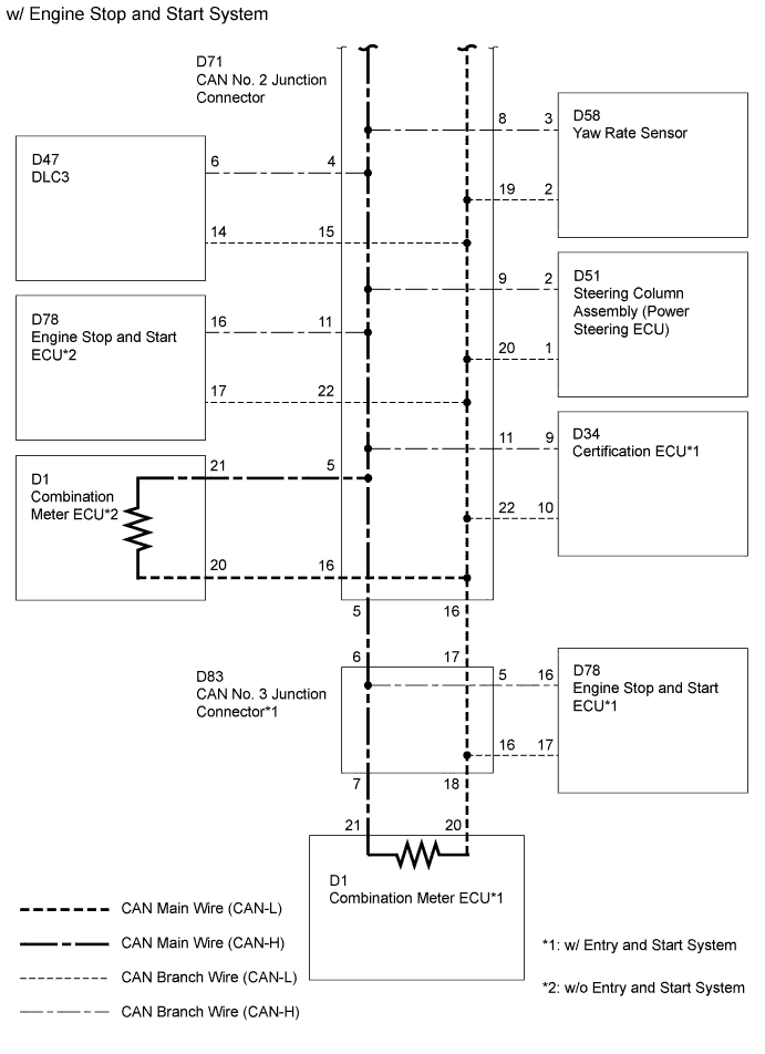
INSPECTION PROCEDURE
Note
-
Turn the ignition switch off before measuring the resistances of the CAN main wire and the CAN branch wire.
-
After the ignition switch is turned off, check that the key reminder warning system and light reminder warning system are not in operation.
-
Before measuring the resistance, leave the vehicle as is for at least 1 minute and do not operate the ignition switch, any other switches or the doors. If doors need to be opened in order to check connectors, open the doors and leave them open.
Tech Tips
Operating the ignition switch, any switches or any doors triggers related ECU and sensor communication with the CAN, which causes resistance variation.
PROCEDURE
-
SYSTEM CHECK
-
Check the vehicle specifications.
Result Result Proceed to w/o Stop and Start System A w/ Stop and Start System B
B 
CHECK CAN BUS WIRE (MAIN WIRE FOR DISCONNECTION, CAN BUS LINES FOR SHORT CIRCUIT) Click here
A 
-
-
CHECK CAN BUS WIRE (MAIN WIRE FOR DISCONNECTION, CAN BUS LINES FOR SHORT CIRCUIT)
-
Turn the ignition switch off.
-
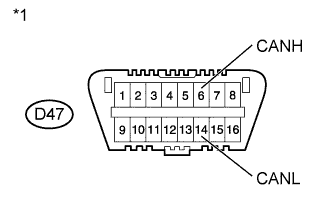
Text in Illustration *1 Front view of DLC3 Measure the resistance according to the value(s) in the table below.
Standard Resistance Tester Connection Switch Condition Specified Condition Proceed to D47-6 (CANH) - D47-14 (CANL) Ignition switch off 54 to 69 Ω A D47-6 (CANH) - D47-14 (CANL) Ignition switch off 70 Ω or higher B D47-6 (CANH) - D47-14 (CANL) Ignition switch off 53 Ω or less C
B 
CHECK CAN MAIN WIRE FOR DISCONNECTION Click here
C
CHECK CAN BUS LINES FOR SHORT CIRCUIT Click here
A
-
-
CHECK FOR SHORT TO B+ IN CAN BUS WIRE
-
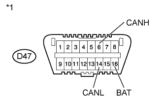
Text in Illustration *1 Front view of DLC3 Measure the resistance according to the value(s) in the table below.
Standard Resistance Tester Connection Switch Condition Specified Condition D47-6 (CANH) - D47-16 (BAT) Ignition switch off 6 kΩ or higher D47-14 (CANL) - D47-16 (BAT) Ignition switch off 6 kΩ or higher
NG
CHECK CAN BUS LINE FOR SHORT TO +B Click here
OK
-
-
CHECK CAN BUS LINE FOR SHORT TO GND
-
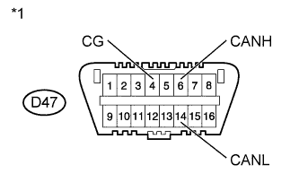
Text in Illustration *1 Front view of DLC3 Measure the resistance according to the value(s) in the table below.
Standard Resistance Tester Connection Switch Condition Specified Condition D47-6 (CANH) - D47-4 (CG) Ignition switch off 200 Ω or higher D47-14 (CANL) - D47-4 (CG) Ignition switch off 200 Ω or higher
NG
CHECK CAN BUS LINE FOR SHORT TO GND Click here
OK 
HOW TO PROCEED WITH TROUBLESHOOTING Click here
-
-
CHECK CAN BUS WIRE (MAIN WIRE FOR DISCONNECTION, CAN BUS LINES FOR SHORT CIRCUIT)
-
Turn the ignition switch off.
-
Text in Illustration *1 Front view of DLC3 Measure the resistance according to the value(s) in the table below.
Standard Resistance Tester Connection Switch Condition Specified Condition Proceed to D47-6 (CANH) - D47-14 (CANL) Ignition switch off 54 to 69 Ω A D47-6 (CANH) - D47-14 (CANL) Ignition switch off 70 Ω or higher B D47-6 (CANH) - D47-14 (CANL) Ignition switch off 53 Ω or less C
B
CHECK CAN MAIN WIRE FOR DISCONNECTION Click here
C
CHECK CAN BUS LINES FOR SHORT CIRCUIT Click here
A
-
-
CHECK FOR SHORT TO B+ IN CAN BUS WIRE
-
Text in Illustration *1 Front view of DLC3 Measure the resistance according to the value(s) in the table below.
Standard Resistance Tester Connection Switch Condition Specified Condition D47-6 (CANH) - D47-16 (BAT) Ignition switch off 6 kΩ or higher D47-14 (CANL) - D47-16 (BAT) Ignition switch off 6 kΩ or higher
NG
CHECK CAN BUS LINE FOR SHORT TO +B Click here
OK
-
-
CHECK CAN BUS LINE FOR SHORT TO GND
-
Text in Illustration *1 Front view of DLC3 Measure the resistance according to the value(s) in the table below.
Standard Resistance Tester Connection Switch Condition Specified Condition D47-6 (CANH) - D47-4 (CG) Ignition switch off 200 Ω or higher D47-14 (CANL) - D47-4 (CG) Ignition switch off 200 Ω or higher
NG
CHECK CAN BUS LINE FOR SHORT TO GND Click here
OK
HOW TO PROCEED WITH TROUBLESHOOTING Click here
-