CAN COMMUNICATION SYSTEM DIAGNOSIS SYSTEM

-
BUS CHECK (COMMUNICATION MALFUNCTION DTC)
Tech Tips
Only CAN communication system DTCs for each ECU can be displayed on the intelligent tester.
-
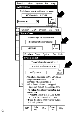
Select "Bus Check" from the "System Select" screen on the intelligent tester.
-
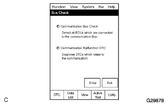
Select "Communication Malfunction DTC" from the "Bus Check" screen, and then select "Enter".
-
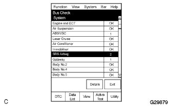
Select the system of the DTC to be checked and select "Details".
-
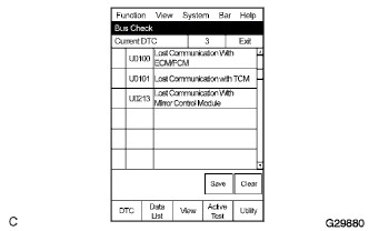
CAN communication system DTCs are displayed.
-
-
BUS CHECK (COMMUNICATION BUS CHECK)
Tech Tips
The ECUs and sensors that are properly connected to the CAN communication system can be displayed using the intelligent tester.
-
Select "Communication Bus Check" from the "Bus Check" screen.
-
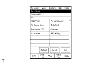
The screen displays the ECUs and sensors that are properly connected to the CAN communication system.
Tech Tips
-
If any properly connected ECUs or sensors are not displayed, there is a communication stop in the system Click here.
-
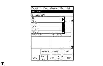
The default item displayed in the combo box is "ALL". When checking the ECUs (sensors) connected to each bus, pull down the combo box and select the bus to be checked from the drop down list. The drop down list displays "ALL", "V Bus", and the names of the remaining buses.
Combo Box Display Content ALL All ECUs (sensors) connected to the CAN bus V Bus ECUs (sensors) connected to the V bus Bus Name ECUs (sensors) connected to the selected bus -
The connection status (shown below) is indicated by the background color displayed behind the system name.
ECU (Sensor) on V Bus Background Color Connection Status White Detected normally Yellow Could not be detected in the past, but is currently detected Red Detected in the past, but cannot be detected now Not displayed Has never been detected ECU (Sensor) with no Data Monitor History Background Color Connection Status White Detected normally Yellow Could not be detected in the past, but is currently detected Red Detected in the past, but cannot be detected now Not displayed Has never been detected ECU (Sensor) with no Data Monitor History Background Color Connection Status White Detected normally Yellow Could not be detected in the past, but is currently detected Red Detected in the past, but cannot be detected now Red Has never been detected but has connection history Not displayed Has never been detected and has no connection history
-
-
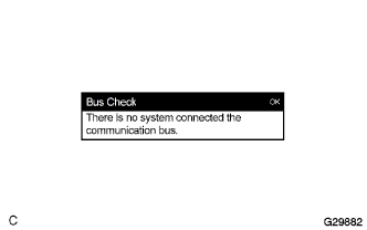
"There is no system connected to the communication bus" is displayed if there are no ECUs or sensors connected to the CAN bus.
-
-
CHECK INSTALLED SYSTEMS (ECU AND SENSOR) THAT ADOPT CAN COMMUNICATION
-
Systems (ECUs and sensors) that adopt CAN communication vary depending on the vehicle's optional settings. Check which systems (ECUs and sensors) are installed on the vehicle.
ECU/Sensor Name Check Method Brake actuator assembly (Skid control ECU) Installed on all vehicles Spiral cable sub-assembly (Steering sensor) Installed on all vehicles Steering column assembly (Power steering ECU) Installed on all vehicles Yaw rate sensor Installed on all vehicles ECM Installed on all vehicles Center airbag sensor assembly Installed on all vehicles Air conditioning amplifier assembly Installed on all vehicles Combination meter assembly (Combination meter ECU) Installed on all vehicles Main body ECU Installed on all vehicles Certification ECU With Entry and Start System Power management control ECU For 1KR-FE Power source control ECU For 1ND-TV
-
-
DTC TABLE BY ECU
Tech Tips
-
In the CAN communication system, CAN communication system DTCs output by the ECU can be displayed by using the intelligent tester.
-
If CAN communication system DTCs are output, trouble cannot be determined solely from the DTCs. Perform troubleshooting according to "How to Proceed with Troubleshooting " Click here.
-
BRAKE ACTUATOR ASSEMBLY (SKID CONTROL ECU)
Tech Tips
DTC communication uses the CAN communication system.
DTC No. Detection Item U0073 Control Module Communication Bus OFF U0100 Lost Communication with ECM/PCM "A" U0123 Lost Communication with Yaw Rate Sensor Module U0124 Lost Communication with Lateral Acceleration Sensor Module U0126 Lost Communication with Steering Angle Sensor Module -
STEERING COLUMN ASSEMBLY (POWER STEERING ECU)
Tech Tips
DTC communication uses the SIL line.
DTC No. Detection Item U0100 Lost Communication with ECM/PCM "A" U0129 Lost Communication with Skid Control ECU U1103 Lost Communication Engine Stop and Start ECU -
AIR CONDITIONING AMPLIFIER ASSEMBLY
Tech Tips
DTC communication uses the CAN communication system.
DTC No. Detection Item U0100 Lost Communication with ECM/PCM "A" U0131 Lost Communication with Electric Power Steering ECU U0142* Lost Communication with Main Body ECU U0155 Lost Communication with Combination Meter *: for Automatic Air Conditioning System
-
ECM
Tech Tips
DTC communication uses the CAN communication system.
DTC No. Detection Item U0129 Lost Communication with Skid Control ECU U1103 Lost Communication Engine Stop and Start ECU -
COMBINATION METER ASSEMBLY (COMBINATION METER ECU)
Tech Tips
DTC communication uses the CAN communication system.
DTC No. Detection Item U0100 Lost Communication with ECM/PCM "A" U0129 Lost Communication with Skid Control ECU U0131 Lost Communication with Electric Power Steering ECU U0151 Lost Communication with Airbag ECU -
MAIN BODY ECU
Tech Tips
DTC communication uses the CAN communication system.
DTC No. Detection Item U0100 Lost Communication with ECM/PCM "A" U0101 Lost Communication with Skid Control ECU U0151 Lost Communication with Airbag ECU U0155 Lost Communication with Combination Meter U0327* Software Incompatibility with Vehicle Security U1133 Lost Communication with Power Management Module *: w/ Entry and Start System
-
CERTIFICATION ECU
Tech Tips
-
DTC communication uses the CAN communication system.
-
Vehicle with entry and start system only.
DTC No. Detection Item U0100 Lost Communication with ECM/PCM "A" U0142 Lost Communication with Skid Control ECU U0155 Lost Communication with Combination Meter -
-
POWER MANAGEMENT CONTROL ECU
Tech Tips
-
DTC communication uses the CAN communication system.
-
for 1KR-FE and 1NR-FE only
DTC No. Detection Item U0100 Lost Communication with ECM/PCM "A" U1002 Lost Communication with Gateway Module -
-
POWER SOURCE CONTROL ECU
Tech Tips
-
DTC communication uses the CAN communication system.
-
for 1ND-TV only
DTC No. Detection Item U0100 Lost Communication with ECM/PCM "A" -
-
ENGINE STOP AND START ECU
Tech Tips
-
DTC communication uses the CAN communication system.
-
Vehicle with engine stop and start system only
DTC No. Detection Item U0100 Lost Communication with ECM/PCM "A" U0121 Lost Communication with Brake System Control Module U0131 Lost Communication with Power Steering Control Module U0140 Lost Communication with Main Body Control Module U0151 Lost Communication with Airbag Control Module U0155 Lost Communication with Combination Meter U0164 Lost Communication with Air Conditioning Amplifier -
-
CENTER AIRBAG SENSOR ASSEMBLY
Tech Tips
The center airbag sensor assembly is connected to the CAN communication system but CAN communication DTCs are not output.
-
SPIRAL CABLE SUB-ASSEMBLY (STEERING SENSOR)
Tech Tips
The steering angle sensor is connected to the CAN communication system but CAN communication DTCs are not output.
-
YAW RATE SENSOR
Tech Tips
The yaw rate sensor is connected to the CAN communication system but CAN communication DTCs are not output.
-
-
DTC COMBINATION TABLE
-
V Bus
DTC Trouble Mode Output from Output DTC Air Conditioning Amplifier Communication Stop Mode Brake Actuator Assembly (Skid Control ECU) Communication Stop Mode ECM Communication Stop Mode Air Conditioning Amplifier Assembly U0100 ○*1 X ○ U0131 ○*1 X X U0142*3 ○*1 X X U0155 ○*1 X X Brake Actuator Assembly (Skid Control ECU) U0073 X ○*1 X U0100 X ○*1 ○ U0123 X ○*1 X U0124 X ○*1 X U0126 X ○*1 X ECM U0129 X ○ ○*1 U1103*7 X X ○*1 Main Body ECU U0100*6 X X ○ U0101*6 X X ○ U0151*6 X X X U0155*6 X X X U0327*2, *6 X X X U1133*6 X X X Combination Meter Assembly (Combination Meter ECU) U0100 X X ○ U0129 X ○ X U0131 X X X U0151 X X X Certification ECU*2 U0100*2 X X ○ U0142*2 X X X U0155*2 X X X Steering Column Assembly (Power Steering ECU) U0100 X X ○ U0129 X ○ X U1103*7 X X X Power Management Control ECU*4 U0100*4 X X ○ Power Source Control ECU*5 U0100*5 X X ○ Engine Stop and Start ECU*7 U0100 X X ○ U0121 X ○ X U0131 X X X U0140 X X X U0151 X X X U0155 X X X U0164 ○ X X Tech Tips
-
○: Stored
-
X: Not stored or may be stored according to the malfunctioning part when one side of the CAN bus wire opens
-
*1: This DTC cannot be output when CAN communication is suspended.
-
*2: w/ Entry and Start System
-
*3: for Automatic Air Conditioning System
-
*4: for 1KR-FE and 1NR-FE with Entry and Start System
-
*5: for 1ND-TV with Entry and Start System
-
*6: w/ Double Locking Function
-
*7: w/ Stop and Start System
DTC Trouble Mode Output from Output DTC Center Airbag Sensor Communication Stop Mode Main Body ECU Communication Stop Mode Combination Meter ECU Communication Stop Mode Air Conditioning Amplifier Assembly U0100 X X X U0131 X X X U0142*3 X ○ X U0155 X X ○ Brake Actuator Assembly (Skid Control ECU) U0073 X X X U0100 X X X U0123 X X X U0124 X X X U0126 X X X ECM U0129 X X X U1103*7 X X X Main Body ECU U0100*6 X ○*1 X U0101*6 X ○*1 X U0151*6 ○ ○*1 X U0155*6 X ○*1 ○ U0327*2, *6 X ○*1 X U1133*6 X ○*1 X Combination Meter Assembly (Combination Meter ECU) U0100 X X ○*1 U0129 X X ○*1 U0131 X X ○*1 U0151 ○ X ○*1 Certification ECU*2 U0100*2 X X X U0142*2 X ○ X U0155*2 X X ○ Steering Column Assembly (Power Steering ECU) U0100 X X X U0129 X X X U1103*7 X X X Power Management Control ECU*4 U0100*4 X X X Power Source Control ECU*4 U0100*5 X X X Engine Stop and Start ECU*7 U0100 X X X U0121 X X X U0131 X X X U0140 X ○ X U0151 ○ X X U0155 X X ○ U0164 X X X Tech Tips
-
○: Stored
-
X: Not stored or may be stored according to the malfunctioning part when one side of the CAN bus wire opens
-
*1: This DTC cannot be output when CAN communication is suspended.
-
*2: w/ Entry and Start System
-
*3: for Automatic Air Conditioning System
-
*4: for 1KR-FE and 1NR-FE with Entry and Start System
-
*5: for 1ND-TV with Entry and Start System
-
*6: w/ Double Locking Function
-
*7: w/ Stop and Start System
DTC Trouble Mode Output from Output DTC Yaw Rate Sensor Communication Stop Mode Certification ECU Communication Stop Mode Steering Angle Sensor Communication Stop Mode Air Conditioning Amplifier Assembly U0100 X X X U0131 X X X U0142*3 X X X U0155 X X X Brake Actuator Assembly (Skid Control ECU) U0073 X X X U0100 X X X U0123 ○ X X U0124 ○ X X U0126 X X ○ ECM U0129 X X X U1103*7 X X X Main Body ECU U0100*6 X X X U0101*6 X X X U0151*6 X X X U0155*6 X X X U0327*2, *6 X ○ X U1133*6 X X X Combination Meter Assembly (Combination Meter ECU) U0100 X X X U0129 X X X U0131 X X X U0151 X X X Certification ECU*2 U0100*2 X ○*1 X U0142*2 X ○*1 X U0155*2 X ○*1 X Steering Column Assembly (Power Steering ECU) U0100 X X X U0129 X X X U1103*7 X X X Power Management Control ECU*4 U0100*4 X X X Power Source Control ECU*5 U0100*5 X X X Engine Stop and Start ECU*7 U0100 X X X U0121 X X X U0131 X X X U0140 X X X U0151 X X X U0155 X X X U0164 X X X Tech Tips
-
○: Stored
-
X: Not stored or may be stored according to the malfunctioning part when one side of the CAN bus wire opens
-
*1: This DTC cannot be output when CAN communication is suspended.
-
*2: w/ Entry and Start System
-
*3: for Automatic Air Conditioning System
-
*4: for 1KR-FE and 1NR-FE with Entry and Start System
-
*5: for 1ND-TV with Entry and Start System
-
*6: w/ Double Locking Function
-
*7: w/ Stop and Start System
DTC Trouble Mode Output from Output DTC Power Steering ECU Communication Stop Mode Power Management Control ECU Communication Stop Mode Power Source Control ECU Communication Stop Mode Engine Stop and Start ECU Communication Stop Mode Air Conditioning Amplifier Assembly U0100 X X X X U0131 ○ X X X U0142*3 X X X X U0155 X X X X Brake Actuator Assembly (Skid Control ECU) U0073 X X X X U0100 X X X X U0123 X X X X U0124 X X X X U0126 X X X X ECM U0129 X X X X U1103*7 X X X ○ Main Body ECU U0100*6 X X X X U0101*6 X X X X U0151*6 X X X X U0155*6 X X X X U0327*2, *6 X X X X U1133*6 X ○ ○ X Combination Meter Assembly (Combination Meter ECU) U0100 X X X X U0129 X X X X U0131 ○ X X X U0151 X X X X Certification ECU*2 U0100*2 X X X X U0142*2 X X X X U0155*2 X X X X Steering Column Assembly (Power Steering ECU) U0100 ○*1 X X X U0129 ○*1 X X X U1103*7 ○*1 X X ○ Power Management Control ECU*4 U0100*4 X ○*1 X X Power Source Control ECU*5 U0100*5 X X ○*1 X Engine Stop and Start ECU*7 U0100 X X X ○*1 U0121 X X X X*1 U0131 ○ X X X*1 U0140 X X X X*1 U0151 X X X X*1 U0155 X X X X*1 U0164 X X X X*1 Tech Tips
-
○: Stored
-
X: Not stored or may be stored according to the malfunctioning part when one side of the CAN bus wire opens
-
*1: This DTC cannot be output when CAN communication is suspended.
-
*2: w/ Entry and Start System
-
*3: for Automatic Air Conditioning System
-
*4: for 1KR-FE and 1NR-FE with Entry and Start System
-
*5: for 1ND-TV with Entry and Start System
-
*6: w/ Double Locking Function
-
*7: w/ Stop and Start System
-
-
Power Management Bus
DTC Trouble Mode Output from Output DTC Power Management Control ECU Communication Stop Mode Power Source Control ECU Communication Stop Mode ECM Communication Stop Mode Power Management Control ECU U0100*2 ○ - ○ U1002*2 ○ - ○ Tech Tips
-
○: Stored
-
-: None
-
*2: w/ Entry and Start System
-
-