LIN COMMUNICATION SYSTEM, Diagnostic DTC:B2786

| DTC Code | DTC Name |
|---|---|
| B2786 | No Response from Steering Lock ECU |
DESCRIPTION
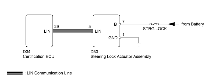
The certification ECU also outputs DTCs when communication with the steering lock actuator assembly is interrupted for more than a specified time.
| DTC No. | DTC Detection Condition | Trouble Area |
|---|---|---|
| B2786 | Communication malfunction occurs between the certification ECU and the steering lock actuator assembly. |
|
WIRING DIAGRAM
INSPECTION PROCEDURE
Tech Tips
When using the intelligent tester, repeatedly turn either front door courtesy light switch off-and-on at intervals of 1.5 seconds or less until communication between the intelligent tester and vehicle begins.
Note
-
Inspect the fuses for this circuit before starting this inspection procedure.
-
Refer to the Service Bulletin for the installation position of the certification ECU.
PROCEDURE
-
CLEAR DTC
-
Clear DTCs Click here.
NEXT 
-
-
CHECK FOR DTC
-
Check for DTCs Click here.
Result Result Proceed to DTC B2786 is output A B2786 and B2785 are output B Tech Tips
When both B2786 and B2785 are output at the same time, troubleshoot B2785 first.
B 
DIAGNOSTIC TROUBLE CODE CHART Click here
A
-
-
CHECK HARNESS AND CONNECTOR (CERTIFICATION ECU - STEERING LOCK ACTUATOR ASSEMBLY)
-
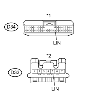
Text in Illustration *1 Front view of wire harness connector
(to Certification ECU)
*2 Front view of wire harness connector
(to Steering Lock Actuator Assembly)
Disconnect the D34 certification ECU connector.
-
Disconnect the D33 steering lock actuator assembly connector.
-
Measure the resistance according to the value(s) in the table below.
Standard Resistance Tester Connection Condition Specified Condition D34-29 (LIN) - D33-5 (LIN) Always Below 1 Ω D33-5 (LIN) - Body ground Always 10 KΩ or higher -
Measure the voltage according to the value(s) in the table below.
Standard Voltage Tester Connection Condition Specified Condition D33-5 (LIN) - Body ground Always Below 0.5 V -
Reconnect the certification ECU connector.
-
Reconnect the steering lock actuator assembly connector.
NG
REPAIR OR REPLACE HARNESS AND CONNECTOR
OK
-
-
CHECK HARNESS AND CONNECTOR (STEERING LOCK ACTUATOR ASSEMBLY - BATTERY AND BODY GROUND)
-
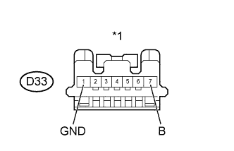
Text in Illustration *1 Front view of wire harness connector
(to Steering Lock Actuator Assembly)
Disconnect the D33 steering lock actuator assembly connector.
-
Measure the voltage according to the value(s) in the table below.
Standard Voltage Tester Connection Condition Specified Condition D33-7 (B) - Body ground Always 11 to 14 V -
Measure the resistance according to the value(s) in the table below.
Standard Resistance Tester Connection Condition Specified Condition D33-1 (GND) - Body ground Always Below 1 Ω -
Reconnect the steering lock actuator assembly connector.
NG
REPAIR OR REPLACE HARNESS AND CONNECTOR
OK
-
-
REPLACE STEERING LOCK ACTUATOR ASSEMBLY NORMAL ONE
-
Replace the steering lock actuator assembly with a normally functioning part Click here.
-
Clear DTCs Click here.
NEXT
-
-
RECONFIRM DTC OUTPUT
-
Recheck for DTCs Click here.
Result Result Proceed to DTC B2786 is not output A DTC B2786 is output B
B
REPLACE CERTIFICATION ECU
A 
END (STEERING LOCK ACTUATOR ASSEMBLY MALFUNCTION)
-