LIN COMMUNICATION SYSTEM, Diagnostic DTC:B2325

| DTC Code | DTC Name |
|---|---|
| B2325 | LIN Communication Bus Malfunction |
DESCRIPTION
The main body ECU monitors LIN communication errors in the door bus. The interruption of communication for 2.6 seconds is 1 error, and when 3 consecutive errors are detected (7.8 seconds), then this DTC is stored.
| DTC No. | DTC Detection Condition | Trouble Area |
|---|---|---|
| B2325 | Door bus error detected 3 times consecutively (LIN communication error) |
|
*1: w/ Double Locking Function
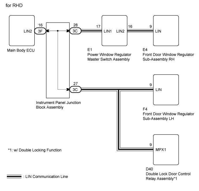
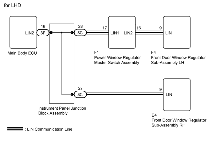
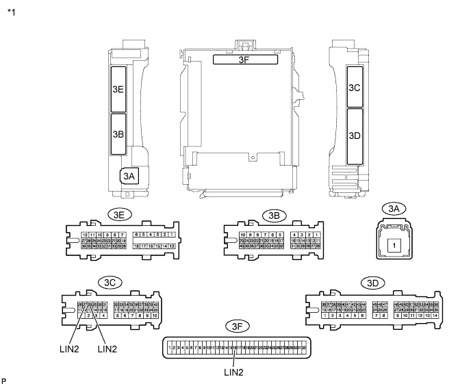
WIRING DIAGRAM
INSPECTION PROCEDURE
Tech Tips
-
When using the intelligent tester, repeatedly turn either front door courtesy light switch off-and-on at intervals of 1.5 seconds or less until communication between the intelligent tester and vehicle begins.
-
When the main body ECU has been replaced with a new part, or when the battery negative terminal is reconnected, the ignition switch condition will be ON. Also, after the battery is disconnected and reconnected, the LIN communication system condition is the same as it was before the battery was disconnected.
PROCEDURE
-
SYSTEM CHECK
-
Check the vehicle specifications.
Result Result Proceed to for RHD A for LHD B
B 
CHECK HARNESS AND CONNECTOR (MASTER SWITCH - REGULATOR LH) Click here
A 
-
-
CHECK HARNESS AND CONNECTOR (MASTER SWITCH - REGULATOR RH)
-
Text in Illustration *1 Front view of wire harness connector
(to Power Window Regulator Master Switch Assembly)
*2 Front view of wire harness connector
(to Front Door Window Regulator Sub-Assembly RH)
Disconnect the E1 power window regulator master switch assembly connector.
-
Disconnect the E4 front door window regulator sub-assembly RH connector.
-
Measure the resistance according to the value(s) in the table below.
Standard Resistance Tester Connection Condition Specified Condition E1-16 (LIN2) - E4-9 (LIN) Always Below 1 Ω E4-9 (LIN) - Body ground Always 10 KΩ or higher -
Measure the voltage according to the value(s) in the table below.
Standard Voltage Tester Connection Condition Specified Condition E4-9 (LIN) - Body ground Always Below 0.5 V -
Reconnect the power window regulator master switch assembly connector.
-
Reconnect the front door window regulator sub-assembly RH connector.
NG 
REPAIR OR REPLACE HARNESS OR CONNECTOR
OK
-
-
CHECK HARNESS AND CONNECTOR (INSTRUMENT PANEL J/B - EACH ECU)
-
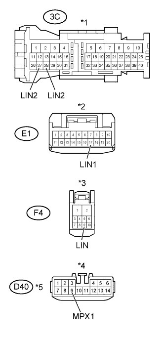
Text in Illustration *1 Front view of wire harness connector
(to Instrument Panel Junction Block Assembly)
*2 Front view of wire harness connector
(to Power Window Regulator Master Switch Assembly)
*3 Front view of wire harness connector
(to Front Door Window Regulator Sub-Assembly LH)
*4 Front view of wire harness connector
(to Double Lock Door Control Relay Assembly)
*5 w/ Double Locking Function Disconnect the 3C instrument panel junction block assembly connector.
-
Disconnect the E1 power window regulator master switch assembly connector.
-
Disconnect the F4 front door window regulator sub-assembly LH connector.
-
Disconnect the D40 double lock door control relay assembly connector.
-
Measure the resistance according to the value(s) in the table below.
Standard Resistance Tester Connection Condition Specified Condition 3C-28 (LIN2) - E1-17 (LIN1) Always Below 1 Ω 3C-27 (LIN2) - F4-9 (LIN) Always Below 1 Ω 3C-27 (LIN2) - D40-9 (MPX1) Always Below 1 Ω 3C-28 (LIN2) - Body ground Always 10 KΩ or higher 3C-27 (LIN2) - Body ground Always 10 KΩ or higher -
Measure the voltage according to the value(s) in the table below.
Standard Voltage Tester Connection Condition Specified Condition 3C-28 (LIN2) - Body ground Always Below 0.5 V 3C-27 (LIN2) - Body ground Always Below 0.5 V -
Reconnect the instrument panel junction block assembly connector.
-
Reconnect the power window regulator master switch assembly connector.
-
Reconnect the front door window regulator sub-assembly LH connector.
-
Reconnect the double lock door control relay assembly connector.
NG
REPAIR OR REPLACE HARNESS OR CONNECTOR
OK
-
-
SYSTEM CHECK
-
Check the vehicle specifications.
Result Result Proceed to w/ Double Locking Function A w/o Double Locking Function B
B
CHECK FOR DTC Click here
A
-
-
CHECK FOR DTC
-
Disconnect the D40 double lock door control relay assembly connector.
-
Connect the 3C instrument panel junction block assembly, E1 power window regulator master switch assembly, E4 front door window regulator sub-assembly RH and F4 front door window regulator sub-assembly LH connectors.
-
Check for DTCs Click here.
Result Result Proceed to DTC B2325 is output A DTC B2325 is not output B
B
REPLACE DOUBLE LOCK DOOR CONTROL RELAY ASSEMBLY NORMAL ONE Click here
A
-
-
CHECK FOR DTC
-
Disconnect the E1 power window regulator master switch assembly connector.
-
Connect the 3C instrument panel junction block assembly, E4 front door window regulator sub-assembly RH, F4 front door window regulator sub-assembly LH and D40 double lock door control relay assembly connectors.
-
Check for DTCs Click here.
Result Result Proceed to DTC B2325 is output A DTC B2325 is not output B
B
REPLACE POWER WINDOW REGULATOR MASTER SWITCH ASSEMBLY NORMAL ONE Click here
A
-
-
CHECK FOR DTC
-
Disconnect the E4 front door window regulator sub-assembly RH connector.
-
Connect the 3C instrument panel junction block assembly, E1 power window regulator master switch assembly, F4 front door window regulator sub-assembly LH and D40 double lock door control relay assembly connectors.
-
Check for DTCs Click here.
Result Result Proceed to DTC B2325 is output A DTC B2325 is not output B
B
REPLACE FRONT DOOR WINDOW REGULATOR SUB-ASSEMBLY RH NORMAL ONE Click here
A
-
-
CHECK FOR DTC
-
Disconnect the F4 front door window regulator sub-assembly LH connector.
-
Connect the 3C instrument panel junction block assembly, E1 power window regulator master switch assembly, E4 front door window regulator sub-assembly RH and D40 double lock door control relay assembly connectors.
-
Check for DTCs Click here.
Result Result Proceed to DTC B2325 is output A DTC B2325 is not output B
B
REPLACE FRONT DOOR WINDOW REGULATOR SUB-ASSEMBLY LH NORMAL ONE Click here
A
-
-
INSPECT INSTRUMENT PANEL JUNCTION BLOCK ASSEMBLY
Text in Illustration *1 Component without harness connected
(Instrument Panel Junction Block Assembly)
-
Remove the instrument panel junction block assembly Click here.
-
Remove the main body ECU from the instrument panel junction block assembly Click here.
-
Measure the resistance according to the value(s) in the table below.
Standard Resistance Tester Connection Condition Specified Condition 3C-27 (LIN2) - 3F-16 (LIN2) Always Below 1 Ω 3C-28 (LIN2) - 3F-16 (LIN2) Always Below 1 Ω 3C-27 (LIN2) - Body ground Always 10 KΩ or higher 3C-28 (LIN2) - Body ground Always 10 KΩ or higher -
Reinstall the main body ECU Click here.
-
Reinstall the instrument panel junction block assembly Click here.
NG
REPLACE INSTRUMENT PANEL JUNCTION BLOCK ASSEMBLY Click here
OK 
REPLACE MAIN BODY ECU Click here
-
-
CHECK HARNESS AND CONNECTOR (MASTER SWITCH - REGULATOR LH)
-
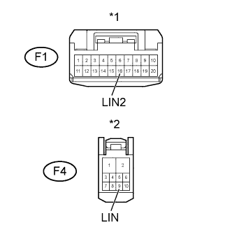
Text in Illustration *1 Front view of wire harness connector
(to Power Window Regulator Master Switch Assembly)
*2 Front view of wire harness connector
(to Front Door Window Regulator Sub-Assembly LH)
Disconnect the F1 power window regulator master switch assembly connector.
-
Disconnect the F4 front door window regulator sub-assembly LH connector.
-
Measure the resistance according to the value(s) in the table below.
Standard Resistance Tester Connection Condition Specified Condition F1-16 (LIN2) - F4-9 (LIN) Always Below 1 Ω F4-9 (LIN) - Body ground Always 10 KΩ or higher -
Measure the voltage according to the value(s) in the table below.
Standard Voltage Tester Connection Condition Specified Condition F4-9 (LIN) - Body ground Always Below 0.5 V -
Reconnect the power window regulator master switch assembly connector.
-
Reconnect the front door window regulator sub-assembly LH connector.
NG
REPAIR OR REPLACE HARNESS OR CONNECTOR
OK
-
-
CHECK HARNESS AND CONNECTOR (INSTRUMENT PANEL J/B - EACH ECU)
-
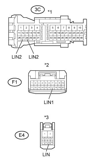
Text in Illustration *1 Front view of wire harness connector
(to Instrument Panel Junction Block Assembly)
*2 Front view of wire harness connector
(to Power Window Regulator Master Switch Assembly)
*3 Front view of wire harness connector
(to Front Door Window Regulator Sub-Assembly RH)
Disconnect the 3C instrument panel junction block assembly connector.
-
Disconnect the F1 power window regulator master switch assembly connector.
-
Disconnect the E4 front door window regulator sub-assembly RH connector.
-
Measure the resistance according to the value(s) in the table below.
Standard Resistance Tester Connection Condition Specified Condition 3C-28 (LIN2) - F1-17 (LIN1) Always Below 1 Ω 3C-27 (LIN2) - E4-9 (LIN) Always Below 1 Ω 3C-28 (LIN2) - Body ground Always 10 KΩ or higher 3C-27 (LIN2) - Body ground Always 10 KΩ or higher -
Measure the voltage according to the value(s) in the table below.
Standard Voltage Tester Connection Condition Specified Condition 3C-28 (LIN2) - Body ground Always Below 0.5 V 3C-27 (LIN2) - Body ground Always Below 0.5 V -
Reconnect the instrument panel junction block assembly connector.
-
Reconnect the power window regulator master switch assembly connector.
-
Reconnect the front door window regulator sub-assembly RH connector.
NG
REPAIR OR REPLACE HARNESS OR CONNECTOR
OK
-
-
CHECK FOR DTC
-
Disconnect the F1 power window regulator master switch assembly connector.
-
Connect the 3C instrument panel junction block assembly, E4 front door window regulator sub-assembly RH and F4 front door window regulator sub-assembly LH connectors.
-
Check for DTCs Click here.
Result Result Proceed to DTC B2325 is output A DTC B2325 is not output B
B
REPLACE POWER WINDOW REGULATOR MASTER SWITCH ASSEMBLY NORMAL ONE Click here
A
-
-
CHECK FOR DTC
-
Disconnect the E4 front door window regulator sub-assembly RH connector.
-
Connect the 3C instrument panel junction block assembly, F1 power window regulator master switch assembly and F4 front door window regulator sub-assembly LH connectors.
-
Check for DTCs Click here.
Result Result Proceed to DTC B2325 is output A DTC B2325 is not output B
B
REPLACE FRONT DOOR WINDOW REGULATOR SUB-ASSEMBLY RH NORMAL ONE Click here
A
-
-
CHECK FOR DTC
-
Disconnect the F4 front door window regulator sub-assembly LH connector.
-
Connect the 3C instrument panel junction block assembly, F1 power window regulator master switch assembly and E4 front door window regulator sub-assembly RH connectors.
-
Check for DTCs Click here.
Result Result Proceed to DTC B2325 is output A DTC B2325 is not output B
B
REPLACE FRONT DOOR WINDOW REGULATOR SUB-ASSEMBLY LH NORMAL ONE Click here
A
-
-
INSPECT INSTRUMENT PANEL JUNCTION BLOCK ASSEMBLY
Text in Illustration *1 Component without harness connected
(Instrument Panel Junction Block Assembly)
-
Remove the instrument panel junction block assembly Click here.
-
Remove the main body ECU from the instrument panel junction block assembly Click here.
-
Measure the resistance according to the value(s) in the table below.
Standard Resistance Tester Connection Condition Specified Condition 3C-27 (LIN2) - 3F-16 (LIN2) Always Below 1 Ω 3C-28 (LIN2) - 3F-16 (LIN2) Always Below 1 Ω 3C-27 (LIN2) - Body ground Always 10 KΩ or higher 3C-28 (LIN2) - Body ground Always 10 KΩ or higher -
Reinstall the main body ECU Click here.
-
Reinstall the instrument panel junction block assembly Click here.
NG
REPLACE INSTRUMENT PANEL JUNCTION BLOCK ASSEMBLY Click here
OK
REPLACE MAIN BODY ECU Click here
-
-
REPLACE DOUBLE LOCK DOOR CONTROL RELAY ASSEMBLY NORMAL ONE
-
Replace the double lock door control relay assembly with a normally functioning part Click here.
-
Clear DTCs Click here.
NEXT
-
-
RECONFIRM DTC OUTPUT
-
Recheck for DTCs Click here.
Result Result Proceed to DTC B2325 is not output A DTC B2325 is output B
B
INSPECT INSTRUMENT PANEL JUNCTION BLOCK ASSEMBLY Click here
A
END (DOUBLE LOCK DOOR CONTROL RELAY ASSEMBLY MALFUNCTION)
-
-
REPLACE POWER WINDOW REGULATOR MASTER SWITCH ASSEMBLY NORMAL ONE
-
Replace the power window regulator master switch assembly with a normally functioning part Click here.
-
Clear DTCs Click here.
NEXT
-
-
RECONFIRM DTC OUTPUT
-
Recheck for DTCs Click here.
Result Result Proceed to DTC B2325 is not output A DTC B2325 is output B
B
INSPECT INSTRUMENT PANEL JUNCTION BLOCK ASSEMBLY Click here
A
END (POWER WINDOW REGULATOR MASTER SWITCH ASSEMBLY MALFUNCTION)
-
-
REPLACE FRONT DOOR WINDOW REGULATOR SUB-ASSEMBLY RH NORMAL ONE
-
Replace the front door window regulator sub-assembly RH with a normally functioning part Click here.
-
Clear DTCs Click here.
NEXT
-
-
RECONFIRM DTC OUTPUT
-
Recheck for DTCs Click here.
Result Result Proceed to DTC B2325 is not output A DTC B2325 is output B
B
INSPECT INSTRUMENT PANEL JUNCTION BLOCK ASSEMBLY Click here
A
END (FRONT DOOR WINDOW REGULATOR SUB-ASSEMBLY RH MALFUNCTION)
-
-
REPLACE FRONT DOOR WINDOW REGULATOR SUB-ASSEMBLY LH NORMAL ONE
-
Replace the front door window regulator sub-assembly LH with a normally functioning part Click here.
-
Clear DTCs Click here.
NEXT
-
-
RECONFIRM DTC OUTPUT
-
Recheck for DTCs Click here.
Result Result Proceed to DTC B2325 is not output A DTC B2325 is output B
B
INSPECT INSTRUMENT PANEL JUNCTION BLOCK ASSEMBLY Click here
A
END (FRONT DOOR WINDOW REGULATOR SUB-ASSEMBLY LH MALFUNCTION)
-
-
INSPECT INSTRUMENT PANEL JUNCTION BLOCK ASSEMBLY
Text in Illustration *1 Component without harness connected
(Instrument Panel Junction Block Assembly)
-
Remove the instrument panel junction block assembly Click here.
-
Remove the main body ECU from the instrument panel junction block assembly Click here.
-
Measure the resistance according to the value(s) in the table below.
Standard Resistance Tester Connection Condition Specified Condition 3C-27 (LIN2) - 3F-16 (LIN2) Always Below 1 Ω 3C-28 (LIN2) - 3F-16 (LIN2) Always Below 1 Ω 3C-27 (LIN2) - Body ground Always 10 KΩ or higher 3C-28 (LIN2) - Body ground Always 10 KΩ or higher -
Reinstall the main body ECU Click here.
-
Reinstall the instrument panel junction block assembly Click here.
NG
REPLACE INSTRUMENT PANEL JUNCTION BLOCK ASSEMBLY Click here
OK
REPLACE MAIN BODY ECU Click here
-