LIN COMMUNICATION SYSTEM, Diagnostic DTC:B2785

| DTC Code | DTC Name |
|---|---|
| B2785 | Communication Malfunction between ECUs Connected by LIN |
DESCRIPTION
The certification ECU monitors communication among all ECUs connected to the certification LIN bus. When the certification ECU detects an interruption in communication among the ECUs connected to the lighting system LIN bus, the interruption is counted at a specified interval, and this DTC is stored when 3 consecutive interruptions are detected. If the interruption in communication among ECUs is corrected, then the DTC is cleared and a history DTC is stored.
| DTC No. | DTC Detection Condition | Trouble Area |
|---|---|---|
| B2785 | The certification ECU detects 3 consecutive malfunctions in the certification LIN bus. |
|
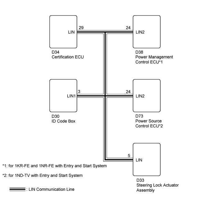
*1: for 1KR-FE and 1NR-FE with Entry and Start System
*2: for 1ND-TV with Entry and Start System
WIRING DIAGRAM
INSPECTION PROCEDURE
Tech Tips
When using the intelligent tester, repeatedly turn either front door courtesy light switch off-and-on at intervals of 1.5 seconds or less until communication between the intelligent tester and vehicle begins.
Note
Refer to the Service Bulletin for the installation position of the certification ECU.
PROCEDURE
-
CHECK HARNESS AND CONNECTOR (CERTIFICATION ECU - EACH ECU)
-
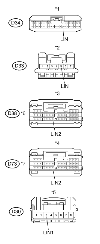
Text in Illustration *1 Front view of wire harness connector
(to Certification ECU)
*2 Front view of wire harness connector
(to Steering Lock Actuator Assembly)
*3 Front view of wire harness connector
(to Power Management Control ECU)
*4 Front view of wire harness connector
(to Power Source Control ECU)
*5 Front view of wire harness connector
(to ID Code Box)
*6 for 1KR-FE and 1NR-FE with Entry and Start System *7 for 1ND-TV with Entry and Start System Disconnect the D34 certification ECU connector.
-
Disconnect the D33 steering lock actuator assembly connector.
-
Disconnect the D38 power management control ECU connector.
-
Disconnect the D73 power source control ECU connector.
-
Disconnect the D30 ID code box connector.
-
Measure the resistance according to the value(s) in the table below.
Standard Resistance Tester Connection Condition Specified Condition D34-29 (LIN) - D33-5 (LIN) Always Below 1 Ω D34-29 (LIN) - D38-24 (LIN2)*1 Always Below 1 Ω D34-29 (LIN) - D73-24 (LIN2)*2 Always Below 1 Ω D34-29 (LIN) - D30-3 (LIN1) Always Below 1 Ω D34-29 (LIN) - Body ground Always 10 KΩ or higher *1: for 1KR-FE and 1NR-FE with Entry and Start System
*2: for 1ND-TV with Entry and Start System
-
Measure the voltage according to the value(s) in the table below.
Standard Voltage Tester Connection Condition Specified Condition D34-29 (LIN) - Body ground Always Below 0.5 V -
Reconnect the certification ECU connector.
-
Reconnect the steering lock actuator assembly connector.
-
Reconnect the power management control ECU connector.
-
Reconnect the power source control ECU connector.
-
Reconnect the ID code box connector.
NG 
REPAIR OR REPLACE HARNESS AND CONNECTOR
OK 
-
-
SYSTEM CHECK
-
Check the vehicle specifications.
Result Result Proceed to for 1KR-FE and 1NR-FE with Entry and Start System A for 1ND-TV with Entry and Start System B
B 
CHECK FOR DTC Click here
A
-
-
CHECK FOR DTC
-
Disconnect the D38 power management control ECU connector.
-
Connect the D34 certification ECU, D33 steering lock actuator assembly and D30 ID code box connectors.
-
Check for DTCs Click here.
Result Result Proceed to DTC B2785 is output A DTC B2785 is not output B
B
REPLACE POWER MANAGEMENT CONTROL ECU NORMAL ONE Click here
A
-
-
CHECK FOR DTC
-
Disconnect the D33 steering lock actuator assembly connector.
-
Connect the D34 certification ECU, D38 power management control ECU and D30 ID code box connectors.
-
Check for DTCs Click here.
Result Result Proceed to DTC B2785 is output A DTC B2785 is not output B
B
REPLACE STEERING LOCK ACTUATOR ASSEMBLY NORMAL ONE Click here
A
-
-
CHECK FOR DTC
-
Disconnect the D30 ID code box connector.
-
Connect the D34 certification ECU, D33 steering lock actuator assembly and D38 power management control ECU connectors.
-
Check for DTCs Click here.
Result Result Proceed to DTC B2785 is output A DTC B2785 is not output B
B
REPLACE ID CODE BOX NORMAL ONE Click here
A 
REPLACE CERTIFICATION ECU
-
-
CHECK FOR DTC
-
Disconnect the D73 power source control ECU connector.
-
Connect the D34 certification ECU, D33 steering lock actuator assembly and D30 ID code box connectors.
-
Check for DTCs Click here.
Result Result Proceed to DTC B2785 is output A DTC B2785 is not output B
B
REPLACE POWER SOURCE CONTROL ECU NORMAL ONE Click here
A
-
-
CHECK FOR DTC
-
Disconnect the D33 steering lock actuator assembly connector.
-
Connect the D34 certification ECU, D73 power source control ECU and D30 ID code box connectors.
-
Check for DTCs Click here.
Result Result Proceed to DTC B2785 is output A DTC B2785 is not output B
B
REPLACE STEERING LOCK ACTUATOR ASSEMBLY NORMAL ONE Click here
A
-
-
CHECK FOR DTC
-
Disconnect the D30 ID code box connector.
-
Connect the D34 certification ECU, D33 steering lock actuator assembly and D73 power source control ECU connectors.
-
Check for DTCs Click here.
Result Result Proceed to DTC B2785 is output A DTC B2785 is not output B
B
REPLACE ID CODE BOX NORMAL ONE Click here
A
REPLACE CERTIFICATION ECU
-
-
REPLACE POWER MANAGEMENT CONTROL ECU NORMAL ONE
-
Replace the power management control ECU with a normally functioning part Click here.
-
Clear DTCs Click here.
NEXT
-
-
RECONFIRM DTC OUTPUT
-
Recheck for DTCs Click here.
Result Result Proceed to DTC B2785 is not output A DTC B2785 is output B
B
REPLACE CERTIFICATION ECU
A
END (POWER MANAGEMENT CONTROL ECU MALFUNCTION)
-
-
REPLACE POWER SOURCE CONTROL ECU NORMAL ONE
-
Replace the power source control ECU with a normally functioning part Click here.
-
Clear DTCs Click here.
NEXT
-
-
RECONFIRM DTC OUTPUT
-
Recheck for DTCs Click here.
Result Result Proceed to DTC B2785 is not output A DTC B2785 is output B
B
REPLACE CERTIFICATION ECU
A
END (POWER SOURCE CONTROL ECU MALFUNCTION)
-
-
REPLACE STEERING LOCK ACTUATOR ASSEMBLY NORMAL ONE
-
Replace the steering lock actuator assembly with a normally functioning part Click here.
-
Clear DTCs Click here.
NEXT
-
-
RECONFIRM DTC OUTPUT
-
Recheck for DTCs Click here.
Result Result Proceed to DTC B2785 is not output A DTC B2785 is output B
B
REPLACE CERTIFICATION ECU
A
END (STEERING LOCK ACTUATOR ASSEMBLY MALFUNCTION)
-
-
REPLACE ID CODE BOX NORMAL ONE
-
Replace the ID code box with a normally functioning part (Refer to the Service Bulletin).
-
Clear DTCs Click here.
NEXT
-
-
RECONFIRM DTC OUTPUT
-
Recheck for DTCs Click here.
Result Result Proceed to DTC B2785 is not output A DTC B2785 is output B
B
REPLACE CERTIFICATION ECU
A
END (ID CODE BOX MALFUNCTION)
-