WIRELESS DOOR LOCK CONTROL SYSTEM (w/ Entry and Start System) TERMINALS OF ECU

-
CHECK MAIN BODY ECU, INSTRUMENT PANEL JUNCTION BLOCK
-
Remove the main body ECU.
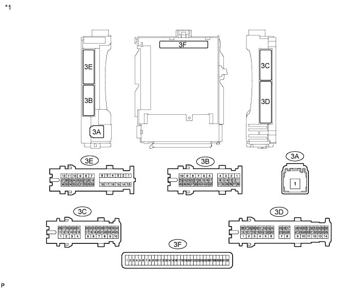
Text in Illustration *1 Instrument Panel Junction Block 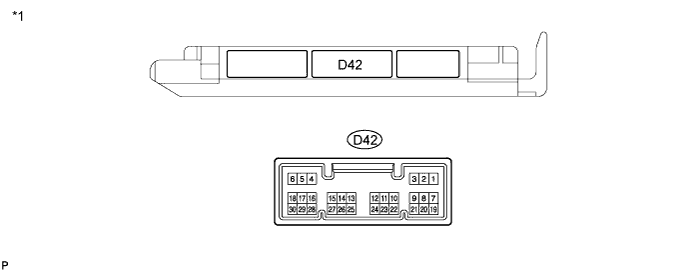
Text in Illustration *1 Main Body ECU (w/ Theft Deterrent System) 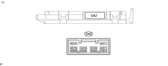
Text in Illustration *1 Main Body ECU (w/o Theft Deterrent System) -
Disconnect the D42 main body ECU connector.
-
Measure the resistance and voltage between each terminal of the wire harness side connectors and body ground.
Terminal No. (Symbol) Wiring Color Terminal Description Condition Specified Condition 3F-2 (FLCY) - Body ground - Front door courtesy light switch LH input Front door LH CLOSED (off) → OPEN (on) 10 kΩ or higher → Below 1 Ω 3F-4 (FRCY) - Body ground - Front door courtesy light switch RH input Front door RH CLOSED (off) → OPEN (on) 10 kΩ or higher → Below 1 Ω 3F-11 (GND1) - Body ground - Ground Always Below 1 Ω 3F-29 (ACC) - Body ground - Ignition power supply (ACC signal) Engine switch on (ACC) → off 11 to 14 V → Below 1 V 3F-30 (ECUB) - Body ground - +B (power system signal system) power supply Always 11 to 14 V 3F-31 (ALTB) - Body ground - +B (power system alternator system) power supply Always 11 to 14 V 3F-32 (IG) - Body ground - Ignition power supply (IG signal) Engine switch on (IG) → off 11 to 14 V → Below 1 V D42-19 (BCTY) - Body ground V - Body ground Back door courtesy light switch input Back door CLOSED (off) → OPEN (on) 10 kΩ or higher → Below 1 Ω Tech Tips
If the result is not as specified, there may be a malfunction on the wire harness side.
-
Reinstall the main body ECU.
-
Reconnect the main body ECU connector.
-
Measure the voltage between each terminal of the wire harness side connectors and body ground.
Terminal No. (Symbol) Wiring Color Terminal Description Condition Specified Condition D42-7 (LSFL) - Body ground R - Body ground Front door unlock detection switch LH input Front door LH UNLOCK → LOCK Below 1 V → 11 to 14 V (or pulse generation) D42-18 (LSFR) - Body ground L - Body ground Front door unlock detection switch RH input Front door RH UNLOCK → LOCK Below 1 V → 11 to 14 V (or pulse generation) D42-19 (BCTY) - Body ground V - Body ground Back door courtesy light switch input Back door CLOSED (off) → OPEN (on) 11 to 14 V (or pulse generation ) → Below 1 V D42-3 (HAZ) - Body ground R - Body ground Hazard warning signal switch input Hazard warning signal switch on Below 1 V Hazard warning signal switch off Pulse generation 3E-24 (FLCY) - Body ground G - Body ground Front door courtesy light switch LH input Front door LH CLOSED (off) → OPEN (on) 11 to 14 V (or pulse generation ) → Below 1 V 3E-35 (FRCY) - Body ground B - Body ground Front door courtesy light switch RH input Front door RH CLOSED (off) → OPEN (on) 11 to 14 V (or pulse generation ) → Below 1 V If the result is not as specified, the main body ECU may have a malfunction.
-
-
CHECK CERTIFICATION ECU
-
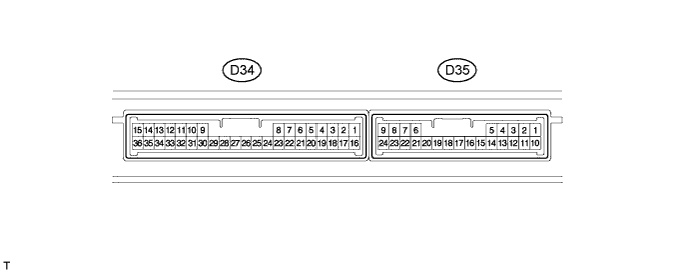
Disconnect the D34 certification ECU connector.
-
Measure the voltage and resistance according to the value(s) in the table below.
Tech Tips
Measure the values on the wire harness side with connector disconnected.
Terminal No. (Symbol) Wiring Color Terminal Description Condition Specified Condition D34-1 (+B) - D34-15 (E) B - W-B +B power supply Always 11 to 14 V D34-15 (E) - Body ground W-B - Body ground Ground Always Below 1 Ω D34-17 (CUTB) - D34-15 (E) W - W-B +B power supply Always 11 to 14 V If the result is not as specified, there may be a malfunction in the wire harness.
-
Reconnect the D34 certification ECU connector.
-
Measure the voltage according to the value(s) in the table below.
Terminal No. (Symbol) Wiring Color Terminal Description Condition Specified Condition D35-5 (RCO) - D34-15 (E) L - W-B Entry door control receiver power source Engine switch off, all doors closed and electrical key switch on Pulse generation → 4.5 to 5.5 V D35-15 (RDA3) - D34-15 (E) LG - W-B Entry door control receiver data input signal Engine switch off 11 to 14 V pulse generation output at regular interval D35-16 (RSSI) - D34-15 (E) P - W-B Entry door control receiver electric wave existence signal All door locked, all doors closed and electrical key switch on 11 to 14 V → Below 2 V If the result is not as specified, the certification ECU may have a malfunction.
-