MAIN BODY ECU INSTALLATION

-
INSTALL MAIN BODY ECU
Note
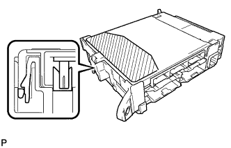
Make sure that there is no foreign matter in the engaging part.
-
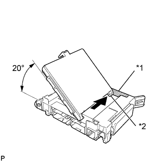
Text in illustration *1 Housing side wall *2 Guide Contact the main body ECU guide against the housing side wall.
Tech Tips
The angle between the junction block and the main body ECU guide should be 20° or more.
-
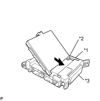
Text in illustration *1 Hosing side wall *2 Guide *3 Fuse area While aligning the guide with the housing side wall, slide the main body ECU toward the fuse area of the junction block.
-
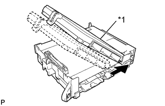
Text in illustration *1 A surface Slide the main body ECU until it contacts the A surface.
Note
Slide the ECU gently. Do not apply strong impact to the side of the main body ECU.
-
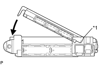
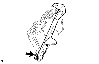
Text in illustration *1 A surface Rotate the main body ECU while holding it against the junction block A surface (axis of rotation).
-
Rotate the main body ECU until it engages with the lock to install it.
Note
-
When pressing the main body ECU, press the shaded section shown in the illustration.
-
A lock sound will be heard when the main body ECU is engaged.
Tech Tips
If a lock sound is not heard, visually check the lock engagement. Check that the height of the main body ECU and junction block match.
-
-
-
INSTALL INSTRUMENT PANEL JUNCTION BLOCK ASSEMBLY (for LHD)
-
Install the bracket with the nut.
-
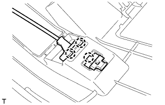
Connect the connectors on the back side.
-
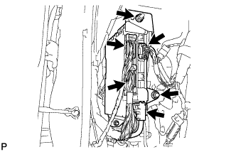
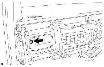
Install the instrument panel junction block with the 2 nuts.
- Torque:
- 5.4 N*m { 55 kgf*cm, 48 in.*lbf }
-
Connect the connectors on the front side.
-
-
INSTALL INSTRUMENT PANEL JUNCTION BLOCK ASSEMBLY (for RHD)
-
Connect the connectors on the back side.
-
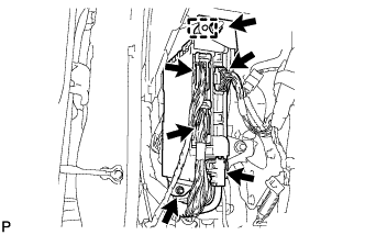
Engage the guide and install the instrument panel junction block with the 2 nuts.
- Torque:
- 5.4 N*m { 55 kgf*cm, 48 in.*lbf }
-
Connect the connectors on the front side.
-
Tighten the heater to register duct installing screw.
-
-
INSTALL LOWER NO. 1 INSTRUMENT PANEL FINISH PANEL (for LHD)
-
Engage the 3 claws and connect the hood lock control lever.
-
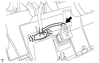
Connect the connector.
-
Engage the 2 claws and connect the DLC3 connector.
-
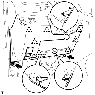
Engage the 2 claws and 7 clips.
-
Install the lower No. 1 instrument panel finish panel with the 2 <C> bolts.
-
-
INSTALL LOWER NO. 2 INSTRUMENT PANEL FINISH PANEL (for RHD)
Tech Tips
Use the same procedure as for the LHD side Click here.
-
INSTALL UPPER INSTRUMENT PANEL SUB-ASSEMBLY (for RHD)
Tech Tips
Use the same procedure as for the LHD side Click here.
-
INSTALL COWL SIDE TRIM BOARD LH
Tech Tips
Use the same procedure as for the RH side Click here.
-
INSTALL FRONT DOOR OPENING TRIM WEATHERSTRIP LH
Tech Tips
Use the same procedure as for the RH side Click here.
-
INSTALL FRONT DOOR SCUFF PLATE LH
Tech Tips
Use the same procedure as for the RH side Click here.