LIN COMMUNICATION SYSTEM TERMINALS OF ECU

-
MAIN BODY ECU AND INSTRUMENT PANEL JUNCTION BLOCK ASSEMBLY
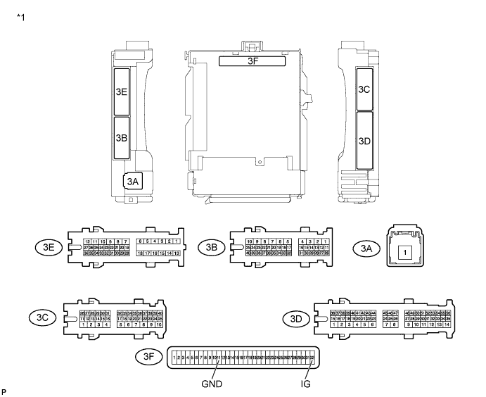
Text in Illustration *1 Component without harness connected
(Instrument Panel Junction Block Assembly)
- -
-
Check main body ECU.
-
Turn the ignition switch off.
-
Remove the main body ECU from the instrument panel junction block assembly Click here.
-
Measure the resistance and voltage according to the value(s) in the table below.
Tech Tips
The instrument panel junction block assembly connectors must all be connected.
Terminal No. (Symbol) Wiring Color Terminal Description Switch Condition Specified Condition 3F-32 (IG) - Body ground - IG power supply Ignition switch ON 11 to 14 V 3F-11 (GND1) - Body ground - Ground Always Below 1 Ω
-
-
Check instrument panel junction block assembly.
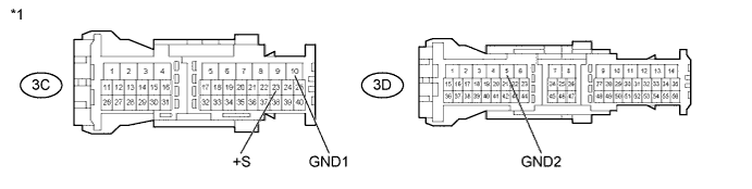
Text in Illustration *1 Front view of wire harness connector
(to Instrument Panel Junction Block Assembly)
- -
-
Disconnect the 3C and 3D instrument panel junction block assembly connector.
-
Measure the resistance and voltage according to the value(s) in the table below.
Terminal No. (Symbol) Wiring Color Terminal Description Switch Condition Specified Condition 3C-10 (GND1) - Body ground W-B - Body ground Ground Always Below 1 Ω 3D-5 (GND2) - Body ground W-B - Body ground Ground Always Below 1 Ω 3C-23 (+S) - Body ground SB - Body ground*1
LG - Body ground*2
IG power supply Ignition switch ON 11 to 14 V *1: w/o Entry and Start System
*2: w/ Entry and Start System
Tech Tips
If the result is not as specified, there may be a malfunction on the wire harness side.
-
-
-
POWER WINDOW REGULATOR MASTER SWITCH ASSEMBLY
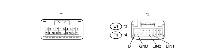
Text in Illustration *1 Component without harness connected
(Power Window Regulator Master Switch Assembly)
*2 Front view of wire harness connector
(to Power Window Regulator Master Switch Assembly)
*3 for RHD *4 for LHD
-
Check the power window regulator master switch assembly.
-
Turn the ignition switch off.
-
Disconnect the E1 or F1 power window regulator master switch assembly connector.
-
Measure the resistance and voltage according to the value(s) in the table below.
for RHD Terminal No. (Symbol) Wiring Color Terminal Description Condition Specified Condition E1-11 (B) - Body ground BR - Body ground Battery power supply Always 11 to 14 V E1-12 (GND) - Body ground W-B - Body ground Ground Always Below 1 Ω for LHD Terminal No. (Symbol) Wiring Color Terminal Description Condition Specified Condition F1-11 (B) - Body ground BR - Body ground Battery power supply Always 11 to 14 V F1-12 (GND) - Body ground W-B - Body ground Ground Always Below 1 Ω Tech Tips
If the result is not as specified, there may be a malfunction on the wire harness side.
-
Reconnect the E1 or F1 power window regulator master switch assembly connector.
-
Measure the pulse according to the value(s) in the table below.
for RHD Terminal No. (Symbol) Wiring Color Terminal Description Switch Condition Specified Condition E1-16 (LIN2) - Body ground P - Body ground LIN communication line Ignition switch ON Pulse generation E1-17 (LIN1) - Body ground P - Body ground LIN communication line Ignition switch ON Pulse generation for LHD Terminal No. (Symbol) Wiring Color Terminal Description Switch Condition Specified Condition F1-16 (LIN2) - Body ground P - Body ground LIN communication line Ignition switch ON Pulse generation F1-17 (LIN1) - Body ground L - Body ground LIN communication line Ignition switch ON Pulse generation Tech Tips
If the result is not as specified, the power window regulator master switch assembly may have a malfunction.
-
-
-
FRONT DOOR WINDOW REGULATOR SUB-ASSEMBLY RH
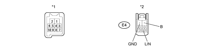
Text in Illustration *1 Component without harness connected
(Front Door Window Regulator Sub-Assembly RH)
*2 Front view of wire harness connector
(to Front Door Window Regulator Sub-Assembly RH)
-
Check the front door window regulator sub-assembly RH.
-
Turn the ignition switch off.
-
Disconnect the E4 front door window regulator sub-assembly RH connector.
-
Measure the resistance and voltage according to the value(s) in the table below.
Terminal No. (Symbol) Wiring Color Terminal Description Condition Specified Condition E4-2 (B) - Body ground W - Body ground*1
B - Body ground*2
Battery power supply Always 11 to 14 V E4-1 (GND) - Body ground W-B - Body ground Ground Always Below 1 Ω *1: for RHD
*2: for LHD
Tech Tips
If the result is not as specified, there may be a malfunction on the wire harness side.
-
Reconnect the E4 front door window regulator sub-assembly RH connector.
-
Measure the pulse according to the value(s) in the table below.
Terminal No. (Symbol) Wiring Color Terminal Description Switch Condition Specified Condition E4-9 (LIN) - Body ground P - Body ground LIN communication line Ignition switch ON Pulse generation Tech Tips
If the result is not as specified, the front door window regulator sub-assembly RH may have a malfunction.
-
-
-
FRONT DOOR WINDOW REGULATOR SUB-ASSEMBLY LH
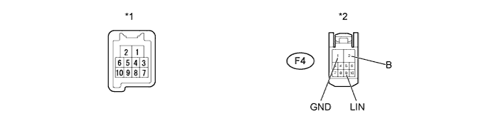
Text in Illustration *1 Component without harness connected
(Front Door Window Regulator Sub-Assembly LH)
*2 Front view of wire harness connector
(to Front Door Window Regulator Sub-Assembly LH)
-
Check the front door window regulator sub-assembly LH.
-
Turn the ignition switch off.
-
Disconnect the F4 front door window regulator sub-assembly LH connector.
-
Measure the resistance and voltage according to the value(s) in the table below.
Terminal No. (Symbol) Wiring Color Terminal Description Condition Specified Condition F4-2 (B) - Body ground B - Body ground*1
W - Body ground*2
Battery power supply Always 11 to 14 V F4-1 (GND) - Body ground W-B - Body ground Ground Always Below 1 Ω *1: for RHD
*2: for LHD
Tech Tips
If the result is not as specified, there may be a malfunction on the wire harness side.
-
Reconnect the F4 front door window regulator sub-assembly LH connector.
-
Measure the pulse according to the value(s) in the table below.
Terminal No. (Symbol) Wiring Color Terminal Description Switch Condition Specified Condition F4-9 (LIN) - Body ground P - Body ground LIN communication line Ignition switch ON Pulse generation Tech Tips
If the result is not as specified, the front door window regulator sub-assembly LH may have a malfunction.
-
-
-
DOUBLE LOCK DOOR CONTROL RELAY ASSEMBLY (w/ Double Locking Function)
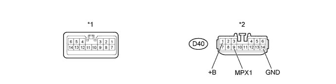
Text in Illustration *1 Component without harness connected
(Double Lock Door Control Relay Assembly)
*2 Front view of wire harness connector
(to Double Lock Door Control Relay Assembly)
-
Check the double lock door control relay assembly.
-
Turn the ignition switch off.
-
Disconnect the D40 double lock door control relay assembly connector.
-
Measure the resistance and voltage according to the value(s) in the table below.
Terminal No. (Symbol) Wiring Color Terminal Description Condition Specified Condition D40-1 (+B) - Body ground W - Body ground Battery power supply Always 11 to 14 V D40-14 (GND) - Body ground W-B - Body ground Ground Always Below 1 Ω Tech Tips
If the result is not as specified, there may be a malfunction on the wire harness side.
-
Reconnect the D40 double lock door control relay assembly connector.
-
Measure the pulse according to the value(s) in the table below.
Terminal No. (Symbol) Wiring Color Terminal Description Switch Condition Specified Condition D40-9 (MPX1) - Body ground P - Body ground LIN communication line Ignition switch ON Pulse generation Tech Tips
If the result is not as specified, the double lock door control relay assembly may have a malfunction.
-
-
-
CERTIFICATION ECU (w/ Entry and Start System)
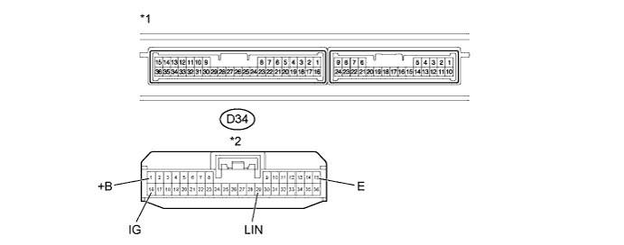
Text in Illustration *1 Component without harness connected
(Certification ECU)
*2 Front view of wire harness connector
(to Certification ECU)
-
Check the certification ECU.
-
Turn the ignition switch off.
-
Disconnect the D34 certification ECU connector.
-
Measure the resistance and voltage according to the value(s) in the table below.
Terminal No. (Symbol) Wiring Color Terminal Description Switch Condition Specified Condition D34-1 (+B) - Body ground B - Body ground Battery power supply Always 11 to 14 V D34-16 (IG) - Body ground V - Body ground IG power supply Ignition switch ON 11 to 14 V D34-15 (E) - Body ground W-B - Body ground Ground Always Below 1 Ω Tech Tips
If the result is not as specified, there may be a malfunction on the wire harness side.
-
Reconnect the D34 certification ECU connector.
-
Measure the pulse according to the value(s) in the table below.
Terminal No. (Symbol) Wiring Color Terminal Description Switch Condition Specified Condition D34-29 (LIN) - Body ground L - Body ground LIN communication line Ignition switch ON Pulse generation Tech Tips
If the result is not as specified, the certification ECU may have a malfunction.
-
-
-
STEERING LOCK ACTUATOR ASSEMBLY
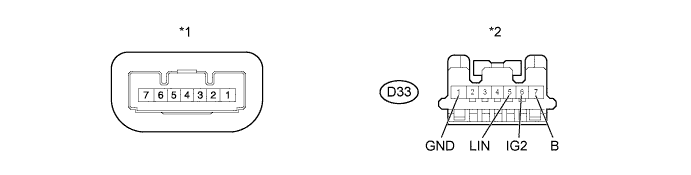
Text in Illustration *1 Component without harness connected
(Steering Lock Actuator Assembly)
*2 Front view of wire harness connector
(to Steering Lock Actuator Assembly)
-
Check the steering lock actuator assembly.
-
Turn the ignition switch off.
-
Disconnect the D33 steering lock actuator assembly connector.
-
Measure the resistance and voltage according to the value(s) in the table below.
Terminal No. (Symbol) Wiring Color Terminal Description Switch Condition Specified Condition D33-6 (IG2) - Body ground L - Body ground IG power supply Ignition switch ON 11 to 14 V D33-7 (B) - Body ground P - Body ground Battery power supply Always 11 to 14 V D33-1 (GND) - Body ground W-B - Body ground Ground Always Below 1 Ω Tech Tips
If the result is not as specified, there may be a malfunction on the wire harness side.
-
Reconnect the D33 steering lock actuator assembly connector.
-
Measure the pulse according to the value(s) in the table below.
Terminal No. (Symbol) Wiring Color Terminal Description Switch Condition Specified Condition D33-5 (LIN) - Body ground G - Body ground LIN communication line Ignition switch ON Pulse generation Tech Tips
If the result is not as specified, the certification ECU may have a malfunction.
-
-
-
ID CODE BOX (w/ Entry and Start System)
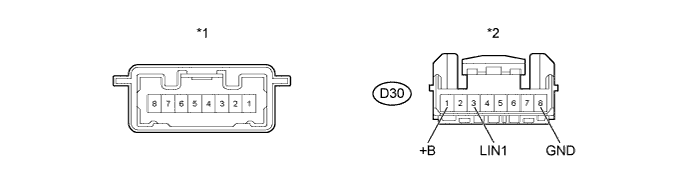
Text in Illustration *1 Component without harness connected
(ID Code Box)
*2 Front view of wire harness connector
(to ID Code Box)
-
Check the ID code box.
-
Turn the ignition switch off.
-
Disconnect the D30 ID code box connector.
-
Measure the resistance and voltage according to the value(s) in the table below.
Terminal No. (Symbol) Wiring Color Terminal Description Condition Specified Condition D30-1 (+B) - Body ground LG - Body ground*1
P - Body ground*2
Battery power supply Always 11 to 14 V D30-8 (GND) - Body ground W-B - Body ground Ground Always Below 1 Ω Tech Tips
If the result is not as specified, there may be a malfunction on the wire harness side.
-
Reconnect the D30 ID code box connector.
-
Measure the pulse according to the value(s) in the table below.
Terminal No. (Symbol) Wiring Color Terminal Description Switch Condition Specified Condition D30-3 (LIN1) - Body ground LG - Body ground*1
R - Body ground*2
LIN communication line Ignition switch ON Pulse generation *1: for RHD
*2: for LHD
Tech Tips
If the result is not as specified, the ID code box may have a malfunction.
-
-
-
POWER MANAGEMENT CONTROL ECU (for 1KR-FE and 1NR-FE with Entry and Start System)
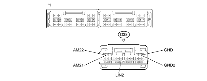
Text in Illustration *1 Component without harness connected
(Power Management Control ECU)
*2 Front view of wire harness connector
(to Power Management Control ECU)
-
Check the power management control ECU.
-
Turn the ignition switch off.
-
Disconnect the D38 power management control ECU connector.
-
Measure the resistance and voltage according to the value(s) in the table below.
Terminal No. (Symbol) Wiring Color Terminal Description Condition Specified Condition D38-1 (AM22) - Body ground L - Body ground Battery power supply Always 11 to 14 V D38-2 (AM21) - Body ground R - Body ground Battery power supply Always 11 to 14 V D38-5 (GND2) - Body ground W-B - Body ground Ground Always Below 1 Ω D38-6 (GND) - Body ground W-B - Body ground Ground Always Below 1 Ω Tech Tips
If the result is not as specified, there may be a malfunction on the wire harness side.
-
Reconnect the D38 power management control ECU connector.
-
Measure the pulse according to the value(s) in the table below.
Terminal No. (Symbol) Wiring Color Terminal Description Switch Condition Specified Condition D38-24 (LIN2) - Body ground P - Body ground LIN communication line Ignition switch ON Pulse generation Tech Tips
If the result is not as specified, the power management control ECU may have a malfunction.
-
-
-
POWER SOURCE CONTROL ECU (for 1ND-TV with Entry and Start System)
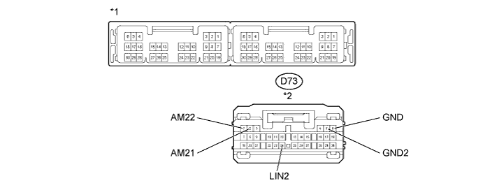
Text in Illustration *1 Component without harness connected
(Power Source Control ECU)
*2 Front view of wire harness connector
(to Power Source Control ECU)
-
Check the power source control ECU.
-
Turn the ignition switch off.
-
Disconnect the D73 power source control ECU connector.
-
Measure the resistance and voltage according to the value(s) in the table below.
Terminal No. (Symbol) Wiring Color Terminal Description Condition Specified Condition D73-1 (AM22) - Body ground L - Body ground Battery power supply Always 11 to 14 V D73-2 (AM21) - Body ground R - Body ground Battery power supply Always 11 to 14 V D73-5 (GND2) - Body ground W-B - Body ground Ground Always Below 1 Ω D73-6 (GND) - Body ground W-B - Body ground Ground Always Below 1 Ω Tech Tips
If the result is not as specified, there may be a malfunction on the wire harness side.
-
Reconnect the D73 power source control ECU connector.
-
Measure the pulse according to the value(s) in the table below.
Terminal No. (Symbol) Wiring Color Terminal Description Switch Condition Specified Condition D73-24 (LIN2) - Body ground P - Body ground LIN communication line Ignition switch ON Pulse generation Tech Tips
If the result is not as specified, the power source control ECU may have a malfunction.
-
-