CHARGING SYSTEM ON-VEHICLE INSPECTION

Note
If the battery is weak or if the engine is difficult to start, recharge the battery and perform inspections again before returning the vehicle to the customer.
-
CHECK BATTERY CONDITION
-
Check the battery for damage and deformation. If severe damage, deformation or leak is found, replace the battery.
-
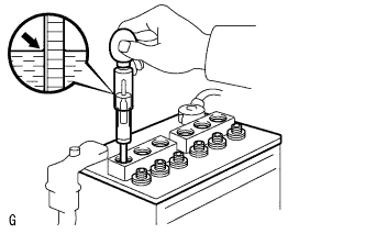
Check the volume of electrolyte quantity in each cell.
-
For batteries that are maintenance-free:
-
If the electrolyte volume is below the lower line, replace the battery.
-
If the electrolyte volume is above the lower line, check the battery voltage when cranking the engine.
-
If the voltage is less than 9.6 V, recharge or replace the battery.
Tech Tips
Before checking the battery voltage, turn off all the electrical systems (headlights, blower motor, rear defogger, etc.).
-
-
For batteries that are not maintenance-free:
-
If the electrolyte volume is below the lower line, add distilled water to each cell. Then, recharge the battery and check the electrolyte specific gravity.
Standard specific gravity 1.25 to 1.29 at 20°C (68°F) If the electrolyte volume is above the lower line, check the battery voltage when cranking the engine. If the battery voltage is less than 9.6 V, recharge or replace the battery.
Tech Tips
Before checking the battery voltage, turn off all the electrical systems (headlights, blower motor, rear defogger, etc.).
-
-
-
-
CHECK BATTERY TERMINAL
-
Check that the battery terminals are not loose or corroded.
If the terminals are corroded, clean them.
-
-
CHECK FUSES
-
Measure the resistance of the fuses.
Standard resistance Below 1 Ω
-
If the results are not as specified, replace the fuses as necessary.
-
-
-
CHECK V-RIBBED BELT
-
Check the belt for wear, cracks or other signs of damage.
If any defects are found, replace the V-ribbed belt:
Tech Tips
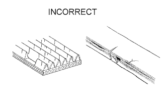
Replace the drive belt if any of the following defects are found:
-
The belt is worn out and the wire is exposed.
-
The cracks reach the wire in more than one place.
-
The belt has pieces missing from the ribs.
-
-
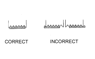
Check that the belt fits properly into the ribbed grooves.
Tech Tips
With your hand, confirm that the belt has not slipped out of the grooves on the bottom of the pulley.
-
-
INSPECT GENERATOR WIRING
-
Check that the wiring is in good condition.
-
-
LISTEN FOR ABNORMAL NOISE FROM GENERATOR
-
Check that the generator does not emit any abnormal noise while the engine is running.
-
-
INSPECT CHARGE WARNING LIGHT CIRCUIT
-
Turn the engine switch to ON. Check that the charge warning light comes on.
-
Start the engine and check that the light goes off.
If the light does not operate as specified, troubleshoot the charge warning light circuit.
-
-
INSPECT CHARGING CIRCUIT WITHOUT LOAD
-
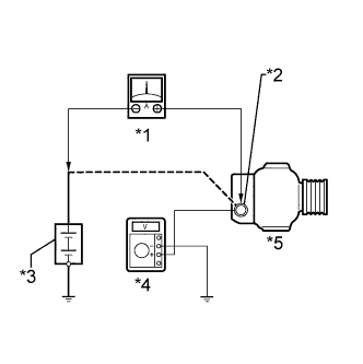
Text in Illustration *1 Ammeter *2 Terminal B *3 Battery *4 Voltmeter *5 Generator Connect a voltmeter and an ammeter to the charging circuit as follows.
Tech Tips
If a battery / generator tester is available, connect the tester to the charging circuit in accordance with the manufacturer's instructions.
-
Disconnect the wire from terminal B of the generator and connect it to the negative (-) lead of the ammeter.
-
Connect the ammeter positive (+) lead to terminal B of the generator.
-
Connect the voltmeter positive (+) lead to terminal B of the generator.
-
Ground the voltmeter negative (-) lead.
-
-
Check the charging circuit.
-
Keep the engine speed at 2000 rpm and check the reading on the ammeter and voltmeter.
Standard current 10 A or less Standard voltage 12.2 to 15.3 V If the result is not as specified, replace the generator.
Tech Tips
If the battery is not fully charged, the ammeter reading will sometimes be more than the standard current.
-
-
-
INSPECT CHARGING CIRCUIT WITH LOAD
-
With the engine running at 2000 rpm, turn the high beam headlights on and turn the heater blower switch to the "HI" position.
-
Check the reading on the ammeter.
Standard current 30 A or more If the ammeter reading is less than the standard current, repair the generator.
Tech Tips
If the battery is fully charged, the indication will sometimes be less than the standard current. If this is the case, add more electrical load (operate the wipers, rear window defogger, etc.) and check the reading on the ammeter again.
-
-
INSPECT CHARGING CONTROL SYSTEM
-
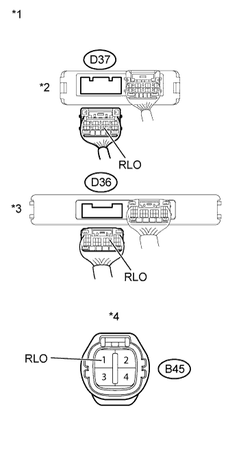
Text in Illustration: *1 Rear view of wire harness connector:
(to Power Management Control ECU)
*2 w/o Entry and Start System *3 w/ Entry and Start System *4 Front view of wire harness connector:
(to Generator)
Check the harness and the connector between the power management control ECU and the generator.
-
Disconnect the generator connector.
-
Disconnect the power management control ECU connector.
-
Measure the resistance according to the value(s) in the table below.
-
w/o Entry and Start System
Standard Resistance Tester Connection Condition Specified Condition D37-14 (RLO) - B45-1 (RLO) Always Below 1 Ω D37-14 (RLO) or B45-1 (RLO) - Body ground Always 10 kΩ or higher -
w/ Entry and Start System
Standard Resistance Tester Connection Condition Specified Condition D36-10 (RLO) - B45-1 (RLO) Always Below 1 Ω D36-10 (RLO) or B45-1 (RLO) - Body ground Always 10 kΩ or higher
-
-
Check the power management control ECU.
-
Start the engine and warm it up.
-
Allow the engine to idle 20 minutes or more.
-
Inspect the power management control ECU using an oscilloscope.
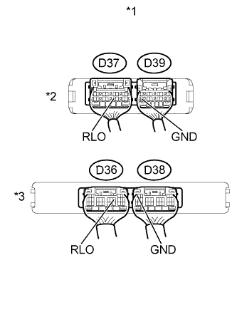
Text in Illustration *1 Rear view of wire harness connector:
(to Power Management Control ECU)
*2 w/o Entry and Start System *3 w/ Entry and Start System -
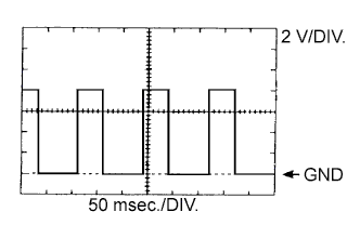
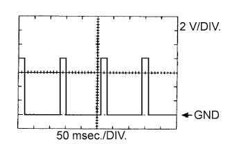
While driving at a constant speed, check the waveform between the terminals of the power management control ECU connector.
-
w/o Entry and Start System
Standard Tester Connection Tool Setting Vehicle Condition Specified Condition D37-14 (RLO) - D39-12 (GND) 2 V/DIV., 50 msec./DIV. After engine warmed up, during charging control, vehicle driven at constant speed Correct waveform as shown in illustration -
w/ Entry and Start System
Standard Tester Connection Tool Setting Vehicle Condition Specified Condition D36-10 (RLO) - D38-6 (GND) 2 V/DIV., 50 msec./DIV. After engine warmed up, during charging control, vehicle driven at constant speed Correct waveform as shown in illustration Tech Tips
A constant value is not output, as the duty ratio varies depending on the electrical load and battery condition.
-
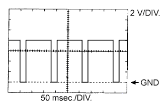
While accelerating, check the waveform between the terminals of the power management control ECU connector.
-
w/o Entry and Start System
Standard Tester Connection Tool Setting Vehicle Condition Specified Condition D37-14 (RLO) - D39-12 (GND) 2 V/DIV., 50 msec./DIV. After engine warmed up, during charging control, vehicle accelerated Correct waveform as shown in illustration -
w/ Entry and Start System
Standard Tester Connection Tool Setting Vehicle Condition Specified Condition D36-10 (RLO) - D38-6 (GND) 2 V/DIV., 50 msec./DIV. After engine warmed up, during charging control, vehicle accelerated Correct waveform as shown in illustration Tech Tips
A constant value is not output, as the duty ratio varies depending on the electrical load and battery condition.
-
While decelerating, check the waveform between the terminals of the power management control ECU connector.
-
w/o Entry and Start System
Standard Tester Connection Tool Setting Vehicle Condition Specified Condition D37-14 (RLO) - D39-12 (GND) 2 V/DIV., 50 msec./DIV. After engine warmed up, during charging control, vehicle decelerated Correct waveform as shown in illustration -
w/ Entry and Start System
Standard Tester Connection Tool Setting Vehicle Condition Specified Condition D36-10 (RLO) - D38-6 (GND) 2 V/DIV., 50 msec./DIV. After engine warmed up, during charging control, vehicle decelerated Correct waveform as shown in illustration Tech Tips
A constant value is not output, as the duty ratio varies depending on the electrical load and battery condition.
-
-