CHARGING SYSTEM TERMINALS OF ECU

-
CHARGING SYSTEM
Tech Tips
The standard voltage between each pair of the power management control ECU terminals is shown in the table below. The appropriate conditions for checking each pair of the terminals are also indicated.
The result of checks should be compared with the standard voltage for that pair of terminals, displayed in the Specified Condition column.
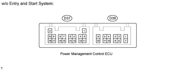
The illustration above can be used as a reference to identify the power management control ECU terminal locations.
Terminal No. (Symbol) Wiring Color Terminal Description Condition Specified Condition D37-14 (RLO) - D39-12 (GND) G - W-B Generator After engine warmed up, during charging control, vehicle driven at constant speed Pulse generation (see waveform 1) After engine warmed up, during charging control, vehicle accelerated Pulse generation (see waveform 2) After engine warmed up, during charging control, vehicle decelerated Pulse generation (see waveform 3) D37-12 (VC) - D37-18 (E2) W - LG Power source of battery current sensor assembly Ignition switch ON 4.5 to 5.5 V D37-15 (THB) - D37-18 (E2) SB - LG Battery temperature sensor Ignition switch ON 0.2 to 4.8 V D37-13 (IB) - D37-18 (E2) Y - LG Battery current sensor Ignition switch ON 0.2 to 4.8 V D37-18 (E2) - Body ground LG - Body ground Sensor ground Always Below 1 Ω D39-8 (AM21) - D39-12 (GND) P - W-B Battery power Always 11 to 14 V D39-1 (INH) - D39-12 (GND) V - W-B Windshield wiper switch assembly Ignition switch ON
Windshield wiper switch "HI" position
11 to 14 V D37-5 (STA) - D39-12 (GND) L - W-B Starter assembly Cranking 5.5 V or more D39-2 (IG2) - D39-12 (GND) L - W-B IG2 relay Ignition switch ON 11 to 14 V D39-9 (PNL) - D39-12 (GND) G - W-B PANEL fuse Light control switch OFF → TAIL Below 1 V → 11 to 14 V 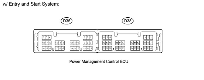
Terminal No. (Symbol) Wiring Color Terminal Description Condition Specified Condition D36-10 (RLO) - D38-6 (GND) G - W-B Generator After engine warmed up, during charging control, vehicle driven at constant speed Pulse generation (see waveform 1) After engine warmed up, during charging control, vehicle accelerated Pulse generation (see waveform 2) After engine warmed up, during charging control, vehicle decelerated Pulse generation (see waveform 3) D36-23 (VC) - D36-25 (E2) W - LG Power source of battery current sensor assembly Ignition switch ON 4.5 to 5.5 V D36-28 (THB) - D36-25 (E2) SB - LG Battery temperature sensor Ignition switch ON 0.2 to 4.8 V D36-30 (IB) - D36-25 (E2) Y - LG Battery current sensor Ignition switch ON 0.2 to 4.8 V D36-25 (E2) - Body ground LG - Body ground Sensor ground Always Below 1 Ω D38-2 (AM21) - D38-6 (GND) R - W-B Battery power Always 11 to 14 V D38-1 (AM22) - D38-6 (GND) L - W-B Battery power Always 11 to 14 V D38-9 (INH) - D38-6 (GND) V - W-B Windshield wiper switch assembly Ignition switch ON
Windshield wiper switch "HI" position
11 to 14 V D36-2 (STA) - D38-6 (GND) L - W-B Starter assembly Cranking 5.5 V or more D38-27 (PNL) - D38-6 (GND) G - W-B PANEL fuse Light control switch OFF → TAIL Below 1 V → 11 to 14 V
-
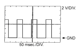
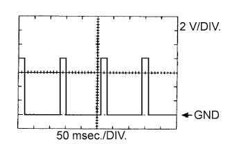
WAVEFORM 1
-
w/o Entry and Start System
Generator Tester Connection Tool Setting Vehicle Condition Specified Condition D37-14 (RLO) - D39-12 (GND) 2 V/DIV., 50 msec./DIV. After engine warmed up, during charging control, vehicle driven at constant speed Correct waveform as shown in illustration -
w/ Entry and Start System
Generator Tester Connection Tool Setting Vehicle Condition Specified Condition D36-10 (RLO) - D38-6 (GND) 2 V/DIV., 50 msec./DIV. After engine warmed up, during charging control, vehicle driven at constant speed Correct waveform as shown in illustration Tech Tips
A constant value is not output, as the duty ratio varies depending on the electrical load and battery condition.
-
-
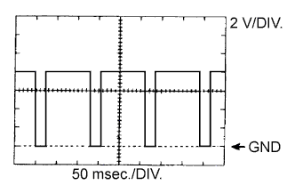
WAVEFORM 2
-
w/o Entry and Start System
Generator Tester Connection Tool Setting Vehicle Condition Specified Condition D37-14 (RLO) - D39-12 (GND) 2 V/DIV., 50 msec./DIV. After engine warmed up, during charging control, vehicle accelerated Correct waveform as shown in illustration -
w/ Entry and Start System
Generator Tester Connection Tool Setting Vehicle Condition Specified Condition D36-10 (RLO) - D38-6 (GND) 2 V/DIV., 50 msec./DIV. After engine warmed up, during charging control, vehicle accelerated Correct waveform as shown in illustration Tech Tips
A constant value is not output, as the duty ratio varies depending on the electrical load and battery condition.
-
-
WAVEFORM 3
-
w/o Entry and Start System
Generator Tester Connection Tool Setting Vehicle Condition Specified Condition D37-14 (RLO) - D39-12 (GND) 2 V/DIV., 50 msec./DIV. After engine warmed up, during charging control, vehicle decelerated Correct waveform as shown in illustration -
w/ Entry and Start System
Generator Tester Connection Tool Setting Vehicle Condition Specified Condition D36-10 (RLO) - D38-6 (GND) 2 V/DIV., 50 msec./DIV. After engine warmed up, during charging control, vehicle decelerated Correct waveform as shown in illustration Tech Tips
A constant value is not output, as the duty ratio varies depending on the electrical load and battery condition.
-
-