AUDIO AND VISUAL SYSTEM AVC-LAN Circuit
DESCRIPTION
Each unit of the audio system connected to the AVC-LAN (communication bus) transfers the signal of each switch by communication.
When a short to +B or short to ground occurs in this AVC-LAN, the audio system will not function normally as the communication is discontinued.
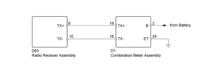
WIRING DIAGRAM
INSPECTION PROCEDURE
PROCEDURE
-
INSPECT RADIO RECEIVER ASSEMBLY (TX+, TX-)
-
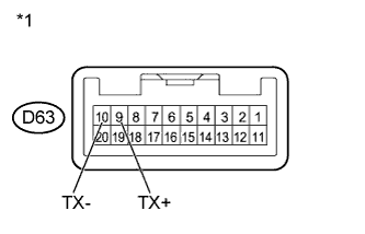
Text in Illustration *1 Component without harness connected
(Radio Receiver Assembly)
Disconnect the D63 radio receiver assembly connector.
-
Measure the resistance according to the value(s) in the table below.
Standard Resistance Tester Connection Condition Specified Condition D63-9 (TX+) - D63-10 (TX-) Always 60 to 80 Ω -
Reconnect the radio receiver assembly connector.
NG 
REPLACE RADIO RECEIVER ASSEMBLY Click here
OK 
-
-
INSPECT COMBINATION METER ASSEMBLY (TX+, TX-)
-
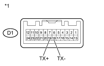
Text in Illustration *1 Component without harness connected
(Combination Meter Assembly)
Disconnect the D1 combination meter assembly connector.
-
Measure the resistance according to the value(s) in the table below.
Standard Resistance Tester Connection Condition Specified Condition D1-19 (TX+) - D1-18 (TX-) Always 60 to 80 Ω -
Reconnect the combination meter assembly connectors.
NG
REPLACE COMBINATION METER ASSEMBLY Click here
OK
-
-
CHECK HARNESS AND CONNECTOR (RADIO RECEIVER ASSEMBLY - COMBINATION METER ASSEMBLY)
-
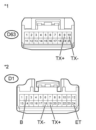
Text in Illustration *1 Front view of wire harness connector
(to Radio Receiver Assembly)
*2 Front view of wire harness connector
(to Combination Meter Assembly)
Disconnect the D63 radio receiver assembly connector.
-
Disconnect the D1 combination meter assembly connector.
-
Measure the resistance according to the value(s) in the table below.
Standard Resistance Tester Connection Condition Specified Condition D63-9 (TX+) - D1-19 (TX+) Always Below 1 Ω D63-10 (TX-) - D1-18 (TX-) D1-19 (TX+) - D1-2 (B) Always 10 kΩ or higher D1-18 (TX-) - D1-24 (ET) -
Reconnect the radio receiver assembly connector.
-
Reconnect the combination meter assembly connector.
NG
REPAIR OR REPLACE HARNESS OR CONNECTOR
OK 
PROCEED TO NEXT SUSPECTED AREA SHOWN IN PROBLEM SYMPTOMS TABLE Click here
-