AUDIO AND VISUAL SYSTEM Speaker Circuit
DESCRIPTION
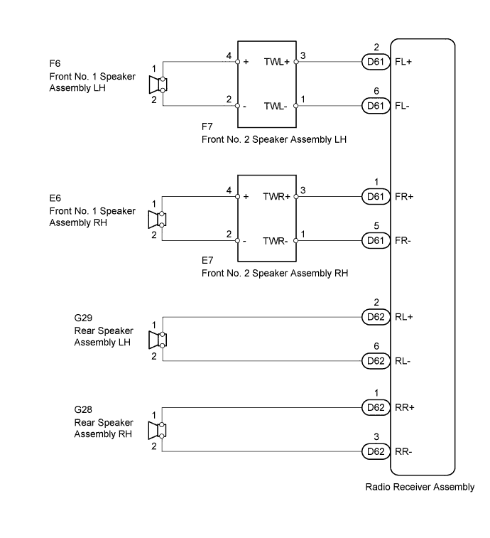
When the radio receiver has a built-in type amplifier, a sound signal is sent from the radio receiver to the speakers via this circuit.
WIRING DIAGRAM
INSPECTION PROCEDURE
PROCEDURE
-
CHECK SPEAKERS
-
Check if sound is emitted from each speaker.
Result Result Proceed to Front No. 1 speakers or front No. 2 speakers have problems A Rear speakers have problems B
B 
INSPECT REAR SPEAKER ASSEMBLY Click here
A 
-
-
INSPECT FRONT NO. 2 SPEAKER ASSEMBLY
-
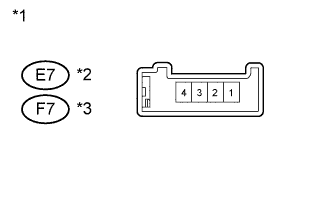
Text in Illustration *1 Component without harness connected
(Front No. 2 Speaker Assembly)
*2 for RH Side *3 for LH Side Disconnect the E7 or F7 front No. 2 speaker assembly connector.
-
Measure the resistance according to the value(s) in the table below.
Standard Resistance: for RH Side Tester Connection Condition Specified Condition E7-1 (TWR-) - E7-3 (TWR+) Always Approximately 4 Ω E7-3 (TWR+) - E7-4 (+) Always Below 1 Ω E7-1 (TWR-) - E7-2 (-) for LH Side Tester Connection Condition Specified Condition F7-1 (TWL-) - F7-3 (TWL+) Always Approximately 4 Ω F7-3 (TWL+) - F7-4 (+) Always Below 1 Ω F7-1 (TWL-) - F7-2 (-) -
Reconnect the front No. 2 speaker assembly connector.
NG 
REPLACE FRONT NO. 2 SPEAKER ASSEMBLY Click here
OK
-
-
CHECK HARNESS AND CONNECTOR (RADIO RECEIVER ASSEMBLY - FRONT NO. 2 SPEAKER ASSEMBLY)
-
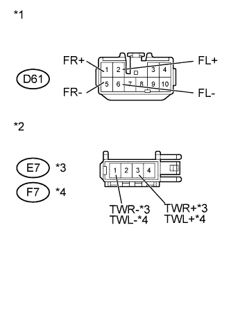
Text in Illustration *1 Front view of wire harness connector
(Radio Receiver Assembly)
*2 Front view of wire harness connector
(to Front No. 2 Speaker Assembly)
*3 for RH Side *4 for LH Side Disconnect the D61 radio receiver assembly connector.
-
Disconnect the E7 or F7 front No. 2 speaker assembly connector.
-
Measure the resistance according to the value(s) in the table below.
Standard Resistance: for RH Side Tester Connection Condition Specified Condition D61-1 (FR+) - E7-3 (TWR+) Always Below 1 Ω D61-5 (FR-) - E7-1 (TWR-) Always Below 1 Ω D61-1 (FR+) - Body ground Always 10 kΩ or higher D61-5 (FR-) - Body ground Always 10 kΩ or higher for LH Side Tester Connection Condition Specified Condition D61-2 (FL+) - F7-3 (TWL+) Always Below 1 Ω D61-6 (FL-) - F7-1 (TWL-) Always Below 1 Ω D61-2 (FL+) - Body ground Always 10 kΩ or higher D61-6 (FL-) - Body ground Always 10 kΩ or higher -
Reconnect the radio receiver assembly connector.
-
Reconnect the front No. 2 speaker assembly connector.
NG
REPAIR OR REPLACE HARNESS OR CONNECTOR
OK
-
-
INSPECT FRONT NO. 1 SPEAKER ASSEMBLY
-
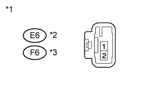
Text in Illustration *1 Component without harness connected
(Front No. 1 Speaker Assembly)
*2 for RH Side *3 for LH Side Disconnect the E6 or F6 front No. 1 speaker assembly connector.
-
Measure the resistance according to the value(s) in the table below.
Standard Resistance: for RH Side Tester Connection Condition Specified Condition E6-1 - E6-2 Always Approximately 4 Ω for LH Side Tester Connection Condition Specified Condition F6-1 - F6-2 Always Approximately 4 Ω -
Reconnect the front No. 1 speaker assembly connector.
NG
REPLACE FRONT NO. 1 SPEAKER ASSEMBLY Click here
OK
-
-
CHECK HARNESS AND CONNECTOR (FRONT NO. 1 SPEAKER ASSEMBLY - FRONT NO. 2 SPEAKER ASSEMBLY)
-
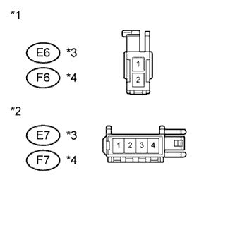
Text in Illustration *1 Front view of wire harness connector
(to Front No. 1 Speaker Assembly)
*2 Front view of wire harness connector
(to Front No. 2 Speaker Assembly)
*3 for RH Side *4 for LH Side Disconnect the E6 or F6 front No. 1 speaker assembly connector.
-
Disconnect the E7 or F7 front No. 2 speaker assembly connector.
-
Measure the resistance according to the value(s) in the table below.
Standard Resistance: for RH Side Tester Connection Condition Specified Condition E6-1 - E7-4 (+) Always Below 1 Ω E6-2 - E7-2 (-) E6-1 - Body ground Always 10 kΩ or higher E6-2 - Body ground for LH Side Tester Connection Condition Specified Condition F6-1 - F7-4 (+) Always Below 1 Ω F6-2 - F7-2 (-) F6-1 - Body ground Always 10 kΩ or higher F6-2 - Body ground -
Reconnect the front No. 1 speaker assembly connector.
-
Reconnect the front No. 2 speaker assembly connector.
NG
REPAIR OR REPLACE HARNESS OR CONNECTOR
OK 
PROCEED TO NEXT SUSPECTED AREA SHOWN IN PROBLEM SYMPTOMS TABLE Click here
-
-
INSPECT REAR SPEAKER ASSEMBLY
-
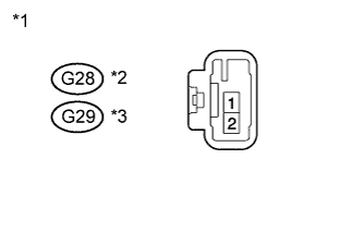
Text in Illustration *1 Component without harness connected
(Rear Speaker Assembly)
*2 for RH Side *3 for LH Side Disconnect the G28 or G29 rear speaker assembly connector.
-
Measure the resistance according to the value(s) in the table below.
Standard Resistance: for RH Side Tester Connection Condition Specified Condition G28-1 - G28-2 Always Approximately 4 Ω for LH Side Tester Connection Condition Specified Condition G29-1 - G29-2 Always Approximately 4 Ω -
Reconnect the rear speaker assembly connector.
NG
REPLACE REAR SPEAKER ASSEMBLY Click here
OK
-
-
CHECK HARNESS AND CONNECTOR (RADIO RECEIVER ASSEMBLY - REAR SPEAKER ASSEMBLY)
-
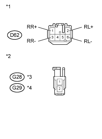
Text in Illustration *1 Front view of wire harness connector
(to Radio Receiver Assembly)
*2 Front view of wire harness connector
(to Rear Speaker Assembly)
*3 for RH Side *4 for LH Side Disconnect the D62 radio receiver assembly connector.
-
Disconnect the G28 or G29 rear speaker assembly connector.
-
Measure the resistance according to the value(s) in the table below.
Standard Resistance: for RH Side Tester Connection Condition Specified Condition D62-1 (RR+) - G28-1 Always Below 1 Ω D62-3 (RR-) - G28-2 D62-1 (RR+) - Body ground Always 10 kΩ or higher D62-3 (RR-) - Body ground for LH Side Tester Connection Condition Specified Condition D62-2 (RL+) - G29-1 Always Below 1 Ω D62-6 (RL-) - G29-2 D62-2 (RL+) - Body ground Always 10 kΩ or higher D62-6 (RL-) - Body ground -
Reconnect the radio receiver assembly connector.
-
Reconnect the rear speaker assembly connector.
NG
REPAIR OR REPLACE HARNESS OR CONNECTOR
OK
PROCEED TO NEXT SUSPECTED AREA SHOWN IN PROBLEM SYMPTOMS TABLE Click here
-