AUDIO AND VISUAL SYSTEM Radio Broadcast cannot be Received (Bad Reception)
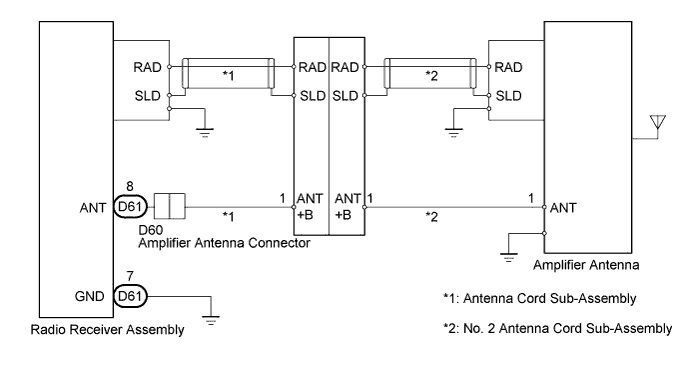
WIRING DIAGRAM
INSPECTION PROCEDURE
PROCEDURE
-
CHECK RADIO RECEIVER ASSEMBLY
-
Check if the radio auto-search functions properly.
-
Tune the radio using the auto-search function and check that it operates normally.
OK The radio auto-search functions properly.
-
NG 
CHECK OPTIONAL COMPONENTS Click here
OK 
END
-
-
CHECK OPTIONAL COMPONENTS
-
Check if any optional components, such as a telephone antenna, are installed.
OK Optional component(s) installed.
NG
CHECK ANTENNA FOR NOISE PRODUCTION Click here
OK
EFFECT FROM OPTIONAL COMPONENTS
-
-
CHECK ANTENNA FOR NOISE PRODUCTION
-
With the ignition switch to ACC, turn on the radio and select the AM mode.
-
Remove the roof antenna pole sub-assembly.
-
Place the tip of a screwdriver on the antenna and check that noise is heard from the speaker.
OK Noise occurs. -
Install the roof antenna pole sub-assembly.
NG
CHECK INSTALLATION OF ANTENNA GROUND Click here
OK
REPLACE RADIO RECEIVER ASSEMBLY Click here
-
-
CHECK INSTALLATION OF ANTENNA GROUND
-
Check that the antenna amplifier ground is securely fastened to the body.
OK Ground is securely fastened to body. -
Check that the No. 2 antenna cord sub-assembly ground is securely fastened to the body.
OK Ground is securely fastened to body.
NG 
CORRECTLY INSTALL GROUND
OK 
-
-
CHECK AMPLIFIER ANTENNA ASSEMBLY
-
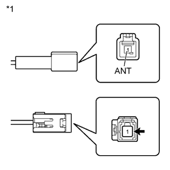
Text in Illustration *1 Front view of wire harness connector
(to No. 2 Antenna Cord Sub-Assembly)
Disconnect the amplifier antenna connectors.
-
With the ignition switch to ON, turn on the radio and select the AM mode.
-
Place the tip of a screwdriver against the metal terminal of the No. 2 antenna cord sub-assembly and check that noise is heard from the speaker.
OK Noise occurs. -
Measure the voltage according to the value(s) in the table below.
Standard Voltage Tester Connection Condition Specified Condition 1(ANT) - Body ground During radio (AM) reception 11 to 14 V -
Reconnect the amplifier antenna connectors.
NG
CHECK NO. 2 ANTENNA CORD SUB-ASSEMBLY Click here
OK
REPLACE ANTENNA AMPLIFIER ASSEMBLY Click here
-
-
CHECK NO. 2 ANTENNA CORD SUB-ASSEMBLY
-

Text in Illustration *1 Front view of wire harness connector
(to Antenna Cord Sub-Assembly)
Disconnect the antenna cord sub-assembly connector.
-
With the ignition switch to ON, turn on the radio and select the AM mode.
-
Place the tip of a screwdriver against the metal terminal of the antenna cord sub-assembly and check that noise is heard from the speaker.
OK Noise occurs. -
Measure the voltage according to the value(s) in the table below.
Standard Voltage Tester Connection Condition Specified Condition 1(ANT +B) - Body ground During radio (AM) reception 11 to 14 V -
Reconnect the antenna cord sub-assembly connector.
NG
CHECK ANTENNA CORD SUB-ASSEMBLY Click here
OK
REPLACE NO. 2 ANTENNA CORD SUB-ASSEMBLY Click here
-
-
CHECK ANTENNA CORD SUB-ASSEMBLY
-
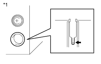
Text in Illustration *1 Component without antenna plug
(to Radio Receiver Assembly)
Remove the antenna plug of the radio receiver assembly.
-
With the radio receiver connector connected, turn the ignition switch to ACC.
-
Turn on the radio and select the AM mode.
-
Place the tip of a screwdriver or a piece of metal, such as a thin wire, on the antenna jack of the radio receiver. Check that noise is heard from the speakers.
OK Noise occurs. -
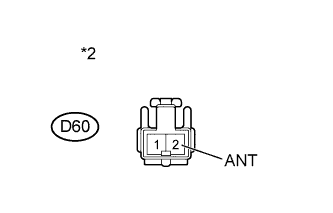
Text in Illustration *1 Front view of wire harness connector
(to Antenna Cord Sub-Assembly)
Disconnect the D60 amplifier antenna connector.
-
Measure the voltage according to the value(s) in the table below.
Standard Voltage Tester Connection Condition Specified Condition D60-2(ANT) - Body ground During radio (AM) reception 11 to 14 V -
Reconnect the amplifier antenna connector.
-
Install the antenna plug.
NG
CHECK HARNESS AND CONNECTOR (RADIO RECEIVER ASSEMBLY - ANTENNA CORD SUB-ASSEMBLY) Click here
OK
REPLACE ANTENNA CORD SUB-ASSEMBLY Click here
-
-
CHECK HARNESS AND CONNECTOR (RADIO RECEIVER ASSEMBLY - ANTENNA CORD SUB-ASSEMBLY)
-
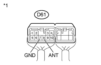
Text in Illustration *1 Component with harness connected
(Radio Receiver Assembly)
Measure the voltage according to the value(s) in the table below.
Standard Voltage Tester Connection Condition Specified Condition D61-8(ANT) - D61-7(GND) During radio (AM) reception 11 to 14 V
NG
REPAIR OR REPLACE HARNESS OR CONNECTOR
OK
REPLACE RADIO RECEIVER ASSEMBLY Click here
-