AUDIO AND VISUAL SYSTEM SYSTEM DESCRIPTION

-
DISC PLAYER OUTLINE
-
A CD player uses a laser pickup to read digital signals recorded on CDs. By converting the digital signals to analog, music and other content can be played.
CAUTION:
Do not look directly at the laser pickup because the CD player uses an invisible laser beam. Be sure to operate the player only as instructed.
Note
-
Do not disassemble any part of the CD player.
-
Do not apply oil to the CD player.
-
Do not insert anything but a CD into the CD player.
-
-
Usable discs
-
The CD player can only play audio CDs, CD-Rs (CD-Recordable), and CD-RWs (CD-ReWritable) that have any of the following marks:
-
-
Precautions for use of discs
Note
-
Copy-protected CDs cannot be played.
-
CD-Rs and CD-RWs may not be played depending on the recording conditions or characteristics of the discs, or due to damage, dirt, or deterioration caused by leaving the discs in the cabin for a long time.
-
Unfinalized CD-Rs and CD-RWs cannot be played.
-
Keep the discs away from dirt. Be careful not to damage the discs or leave your fingerprints on them.
-
Hold discs by the outer edge and center hole with the label side up.
-
Leaving the disc exposed halfway out of the slot for a long time after pressing the disc eject button may cause deformation of the disc, making the disc unusable.
-
If discs have adhesive tape, stickers, CDR labels, or any traces of such labels attached, the discs may not be ejected or player malfunctions may result.
-
Keep the discs away from direct sunlight. (Exposure to direct sunlight may cause deformation of the disc, making the disc unusable.)
-
Do not use odd-shaped CDs because these may cause player malfunctions.
-
Do not use discs whose recording portion is transparent or translucent because they may not be inserted, ejected, or played normally.
Tech Tips
-
When it is cold or raining, if mist forms on the windows, mist and dew may form in the player. In such a case, the CD may skip or the CD may stop playing. Ventilate or dehumidify the cabin for a while before using the player.
-
The CD may skip if the player experiences strong vibrations when the vehicle is driven on rough roads or similar uneven surfaces.
-
-
Cleaning
Note
Do not use a lens cleaner because it may cause a malfunction in the pickup portion of the player.
-
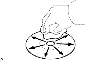
If dirt is on the disc surface, wipe it clean with a soft dry cloth, such as an eyeglass cleaner for plastic lenses, from the inside to the outside in a radial direction.
Note
-
Pressing on the disc by hand or rubbing the disc with a hard cloth may scratch the disc surface.
-
Use of solvent such as a record spray, antistatic agent, alcohol, benzene, or thinner, or a chemical cloth may cause damage to the disc, making the disc unusable.
-
-
-
-
MP3/WMA OUTLINE
-
Playable MP3 file standards
Compatible standard MP3 (MPEG1 LAYER 3, MPEG2 LSF LAYER 3) Compatible sampling frequency
-
MPEG1 LAYER 3: 32, 44.1, 48 (kHz)
-
MPEG2 LSF LAYER 3: 16, 22.05, 24 (kHz)
Compatible bit rate
-
MPEG1 LAYER 3: 64, 80, 96, 112, 128, 160, 192, 224, 256, 320 (kbps)
-
MPEG2 LSF LAYER 3: 64, 80, 96, 112, 128, 144, 160 (kbps)
-
Compatible with VBR
Compatible channel mode Stereo, joint stereo, dual channel, monaural -
-
Playable WMA file standards
Compatible standard WMA Ver. 7, 8, and 9 Compatible sampling frequency 32, 44.1, 48 (kHz) Compatible bit rate
-
Ver. 7, 8: CBR48, 64, 80, 96, 128, 160, 192 (kbps)
-
Ver. 9: CBR48, 64, 80, 96, 128, 160, 192, 256, 320 (kbps)
-
Compatible with playback of channel 2 only
-
-
ID3 tag and WMA tag
-
Additional text information called ID3 tags can be input to MP3 files. Information such as song titles and artist names can be stored.
Tech Tips
This player is compatible with the ID3 tags of ID3 Ver. 1.0 and 1.1, and ID3 Ver. 2.2 and 2.3 (Number of characters complies with ID3 Ver. 1.0 and 1.1.).
-
Additional text information called WMA tags can be input to WMA files. Information such as song titles and artist names can be stored.
-
-
Usable media
-
Only CD-ROMs, CD-Rs (CD-Recordable), and CD-RWs (CD-ReWritable) can be used to play MP3/WMA files.
Note
-
CD-Rs and CD-RWs are more easily affected by a hot and humid environment than discs used for normal audio CDs. For this reason, some CD-Rs and CD-RWs may not be playable.
-
If there are fingerprints or scratches on the disc, the disc may not be playable or the CD may skip.
-
Some CD-Rs and CD-RWs deteriorate if they are left in the cabin for a long time.
-
Keep CD-Rs and CD-RWs in a storage case that is impenetrable to light.
-
-
-
Usable media format
-
Usable media format
Disc format CD-ROM Mode 1, CD-ROM XA Mode 2 Form 1 File format ISO9660 Level 1 and Level 2 (Joliet, Romeo) Tech Tips
-
As for MP3/WMA files written in any format other than those above, the contents of the files may not be playable or the file names or folder names may not be displayed correctly.
-
This player is compatible with multi-session discs and can play CD-Rs and CD-RWs on which MP3/WMA files are added. However, only the first session can be played.
-
Discs whose first session includes both music data and MP3 or WMA format data cannot be played.
-
-
Standard and restrictions
Maximum directory levels 8 levels Maximum number of characters for a folder name/file name 32 characters Maximum number of folders 192 (Including empty folders, route folders, and folders that do not contain MP3/WMA files) Maximum number of files in a disc 255 (Including non-MP3/WMA files)
-
-
File names
-
Only files with an extension of ".mp3" or ".wma" can be recognized and played as MP3 or WMA files.
-
Save MP3 or WMA files with an extension of ".mp3" or ".wma".
Note
If saving non-MP3 or non-WMA files with an extension of ".mp3" or ".wma", those files are wrongly recognized as MP3 or WMA files and played. A loud noise may occur and damage to the speaker may result.
-
-
-
AVC-LAN DESCRIPTION
-
What is AVC-LAN?
AVC-LAN, an abbreviation for "Audio Visual Communication Local Area Network", is a united standard developed by the manufacturers in affiliation with Toyota Motor Corporation. This standard pertains to audio and visual signals as well as switch and communication signals.
-
Purpose:
Recently, car audio systems have rapidly developed and the functions have vastly changed. The conventional car audio system is being integrated with multi-media interfaces similar to those in navigation systems. At the same time, customers are demanding higher quality from their audio systems. This is merely an overview of the standardization background. The specific purposes are as follows:
-
To solve sound problems, etc. caused by using components of different manufacturers through signal standardization.
-
To allow each manufacturer to concentrate on developing products they do best. From this, reasonably priced products can be produced.
Tech Tips
-
If a short to +B or short to ground is detected in the AVC-LAN circuit, communication is interrupted and the audio system will stop functioning.
-
If the audio system has a navigation system installed, the multi-display unit acts as the master unit. If the navigation system is not installed, the audio head unit acts as the master unit instead. If the radio and navigation assembly is installed, it is the master unit.
-
-
-
-
COMMUNICATION SYSTEM OUTLINE
-
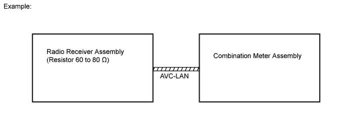
Components of the audio system communicate with each other via the AVC-LAN.
-
The master component of the AVC-LAN is a radio receiver assembly with a 60 to 80 Ω resistor. This is essential for communication.
-
If a short circuit or open circuit occurs in the AVC-LAN circuit, communication is interrupted and the audio system will stop functioning.
-
-
DIAGNOSTIC FUNCTION OUTLINE
-
The audio system has a diagnostic function (the result is indicated on the master unit).
-
A 3-digit hexadecimal component code (physical address) is allocated to each component on the AVC-LAN. Using this code, the component in the diagnostic function can be displayed.
-
-
DIAGNOSTIC TROUBLE CHART
Terms Definitions Physical address (component code)
-
Three-digit code (in hexadecimals) given to each component of the AVC-LAN.
-
Individual symbols provided corresponding to each function.
Logical address Two-digit code (in hexadecimals) given to each function and component unit in each component of AVC-LAN. Tech Tips
Titles for each unit below are stated in the following order: physical address (part name).
-
190 (RADIO RECEIVER)
Logical Address: 01 (Communication Control) DTC Diagnostic Item Diagnostic Content Troubleshooting D6*1 Absence of Master Component With ignition switch to ACC or ON, code related component disconnected from system or master component.
-
Check harness of power supply system of radio receiver.
-
Check harness of communication system of radio receiver.
D7*2 Connection Check Error Code related component disconnected from system or master component after engine start.
-
Check harness of power supply system of radio receiver.
-
Check harness of communication system of radio receiver.
D8*2 No Response to Connection Check Component shown by sub code disconnected from system after engine start.
-
Check harness of power supply system of component shown by sub code.
-
Check harness of communication system of component shown by sub code.
D9*1 Last Mode Error With ignition switch to ACC or ON, audio or visual component that was operating when engine was stopped cannot connect.
-
Check harness of power supply system of component shown by sub code.
-
Check harness of communication system of component shown by sub code.
DD*1 Master Reset (Momentary Interruption) Master component disconnected from system after engine start.
-
Check harness of power supply system of radio receiver.
-
Check harness of communication system of radio receiver.
-
If this error occurs frequently, replace radio receiver.
Tech Tips
*1: May be recorded due to the battery condition or engine start voltage even if no failure is detected.
*2: If the power connector is disconnected after the engine starts, this code is recorded after 180 seconds.
Logical Address: 60 (Tuner) DTC Diagnosis item Diagnosis Content Troubleshooting 12 Tuner Communication Error Communication error between tuner and main micro computer. Replace radio receiver 43 AM Tuner Error AM tuner is abnormal. Replace radio receiver 44 FM Tuner Error FM tuner is abnormal. Replace radio receiver Logical Address: 62 (CD Player) DTC Diagnosis item Diagnosis Content Troubleshooting 10 CD Mechanical Error CD mechanical error was detected when the radio receiver was not loading or ejecting a CD. Replace radio receiver 42 No Disc Readout Disc cannot be read.
-
Inspect CD.
-
Replace radio receiver.
44 CD Player Error Error detected in CD player.
-
Inspect CD.
-
Replace radio receiver.
45 EJECT Error Disc cannot be ejected. Replace radio receiver. 46 Scratched / Reversed Disc Scratches or dirt found on CD surface or CD set upside down. Inspect CD. -
-