STEERING COLUMN ASSEMBLY INSTALLATION

-
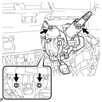
INSTALL STEERING COLUMN ASSEMBLY
-
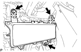
Install the steering column assembly onto the instrument panel reinforcement assembly with the 4 nuts.
- Torque:
- 25 N*m { 255 kgf*cm, 18 ft.*lbf }
-
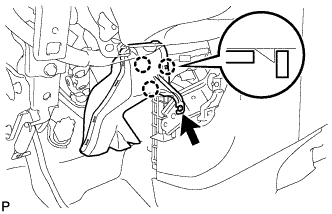
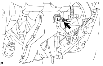
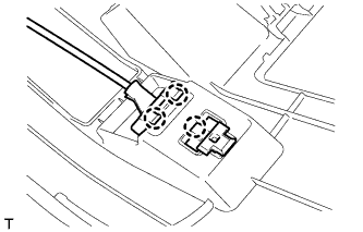
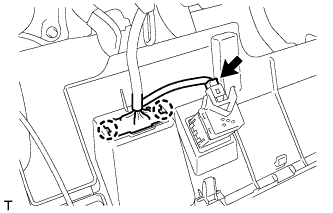
Connect all the connectors and clamp the wire harnesses onto the steering column assembly bracket.
-
-
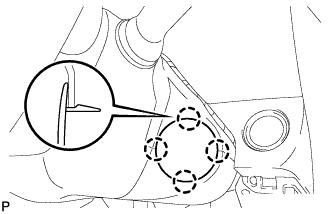
INSTALL NO. 2 STEERING INTERMEDIATE SHAFT ASSEMBLY
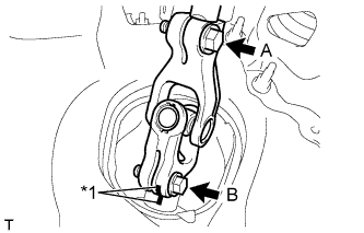
Text in Illustration *1 Matchmark
-
Align the matchmarks on the No. 2 steering intermediate shaft assembly and steering gear assembly and install them with bolt B.
- Torque:
- 35 N*m { 360 kgf*cm, 26 ft.*lbf }
-
Tighten bolt A.
- Torque:
- 35 N*m { 360 kgf*cm, 26 ft.*lbf }
-
-
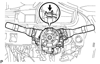
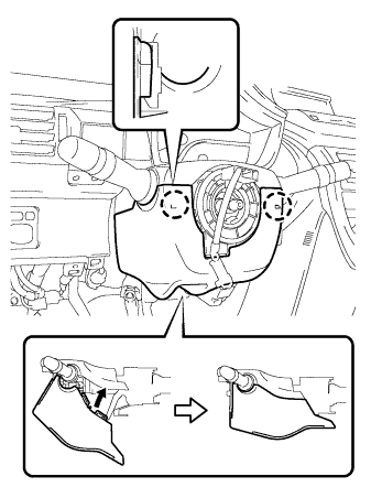
INSTALL COMBINATION SWITCH ASSEMBLY
-
Install the combination switch assembly together with the spiral cable onto the steering column assembly with the clamp
-
Connect all the connectors to the combination with the spiral cable.
-
-
INSTALL STEERING COLUMN UPPER COVER
-
Engage the 3 claws and install the steering column upper cover.
-
-
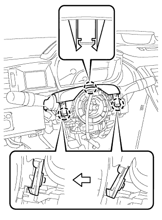
INSTALL STEERING COLUMN LOWER COVER
-
Engage the 2 claws and install the steering column lower cover as shown in the illustration.
-
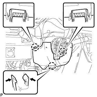
Engage the 3 claws and install the steering column lower cover.
Tech Tips
Press the area around the claw to engage it.
-
-
INSTALL STEERING COLUMN COVER SUPPORT (w/ Smart Entry and Start System)
-
Engage the 4 claws and install the steering column cover support.
-
-
TURN FRONT WHEELS TO FACE STRAIGHT AHEAD
-
ADJUST SPIRAL CABLE
-
Check that the ignition switch is turned off.
-
Check that the cable is disconnected from the negative (-) auxiliary battery terminal.
CAUTION:
Wait at least 90 seconds after disconnecting the cable from the negative (-) auxiliary battery terminal to disable the SRS system.
-
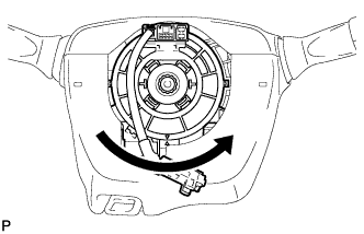
Center the spiral cable.
-
Turn the spiral cable counterclockwise until it locks.
Note
To avoid breaking the spiral cable, turn the spiral cable gently and do not use excessive force.
Tech Tips
The spiral cable turns a maximum of approximately 5 times.
-
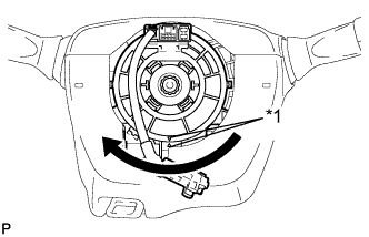
Text in Illustration *1 Alignment mark Turn the spiral cable 2.5 times clockwise from its locked position and align the center marks.
-
-
-
INSTALL STEERING WHEEL ASSEMBLY
-
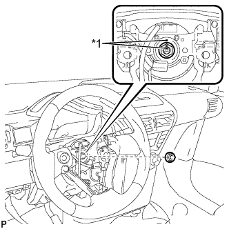
Text in Illustration *1 Matchmark Align the matchmarks and install the steering wheel assembly onto the steering column assembly.
-
Install the nut.
- Torque:
- 50 N*m { 510 kgf*cm, 37 ft.*lbf }
-
Connect all the connectors to the spiral cable.
-
-
INSTALL STEERING PAD
Note
Do not use a steering pad that has been dropped.
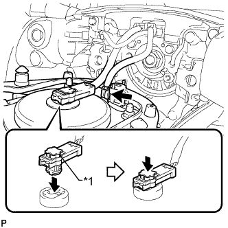
Text in Illustration *1 Locking Button
-
Confirm that the ignition switch is off.
-
Confirm that the cable to the negative battery terminal is disconnected.
CAUTION:
Wait at least 90 seconds after disconnecting the cable from the negative (-) battery terminal to disable the SRS system.
-
Connect the horn terminal.
-
Connect the airbag connector.
Note
-
Match the color of the airbag connector with that of the steering pad assembly, and install the airbag connector.
-
Securely lock the locking button.
-
-
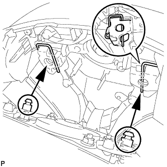
Engage the pins into the spring clips behind the horn button assembly to install the steering pad.
Note
Pull the horn button assembly to ensure that it is securely engaged.
Tech Tips
Install the right-side pin of the horn button assembly first.
-
-
INSTALL NO. 3 AIR DUCT SUB-ASSEMBLY
-
Engage the 3 claws and install the air duct.
-
Install the clip.
-
Connect the connector.
Tech Tips
If the vehicle is equipped with stop and start system, connect the connector.
-
-
INSTALL KNEE AIRBAG ASSEMBLY
-
Engage the 2 guides and install the knee airbag assembly.
-
Install the 3 bolts.
- Torque:
- 10 N*m { 102 kgf*cm, 7 ft.*lbf }
-
-
INSTALL LOWER NO. 1 INSTRUMENT PANEL FINISH PANEL
-
Engage the 3 claws and connect the hood lock control lever.
-
Connect the connector.
-
Engage the 2 claws and connect the DLC3 connector.
-
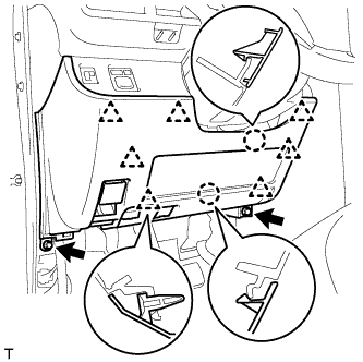
Engage the 2 claws and 7 clips.
-
Install the lower No. 1 instrument panel finish panel with the 2 <C> bolts.
-
-
INSTALL FRONT DOOR OPENING TRIM WEATHERSTRIP LH
-
INSTALL COWL SIDE TRIM BOARD LH
Tech Tips
Use the same procedure as for the RH side.
-
INSTALL FRONT DOOR SCUFF PLATE LH
Tech Tips
Use the same procedure as for the RH side.
-
CONNECT CABLE TO NEGATIVE BATTERY TERMINAL
- Torque:
- 5.4 N*m { 55 kgf*cm, 48 in.*lbf }
-
INSPECT SRS WARNING LIGHT TURNS OFF
-
PERFORM ASSIST MAP WRITING