STEERING COLUMN ASSEMBLY DISASSEMBLY

-
REMOVE NO. 2 STEERING INTERMEDIATE SHAFT ASSEMBLY
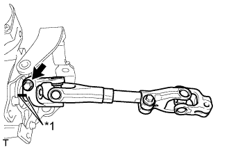
Text in Illustration *1 Matchmark
-
Place matchmarks on the No. 2 steering intermediate shaft assembly and the steering column assembly.
-
Remove bolt and remove the No. 2 steering intermediate shaft assembly from the steering column assembly.
-
-
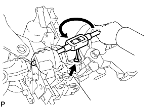
REMOVE STEERING COLUMN UPPER WITH SWITCH BRACKET ASSEMBLY (w/o Smart Entry and Start System)
-
Fix the steering post assembly in a vise between aluminum plates.
Note
Do not overtighten the vise.
-
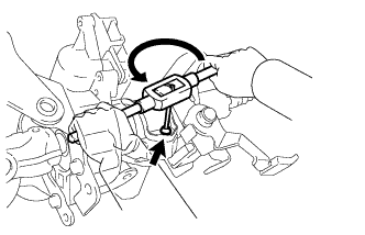
Using a drill, drill a hole in each of the steering lock set bolt, to insert a screw extractor.
-
Using the screw extractor, remove the steering lock set bolt and remove the steering column upper with switch bracket assembly and steering column clamp upper.
-
-
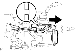
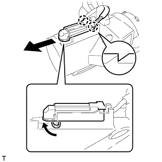
REMOVE TRANSPONDER KEY AMPLIFIER (w/o Smart Entry and Start System)
-
Disengage the 2 claws and slide the transponder key amplifier in the direction shown in the illustration, to detach it from the steering column upper with switch bracket assembly.
-
-
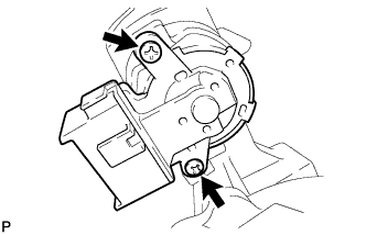
REMOVE IGNITION SWITCH ASSEMBLY (w/o Smart Entry and Start System)
-
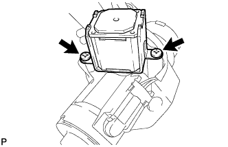
Remove the 2 screws and the ignition switch assembly from the steering column bracket assembly upper.
-
-
REMOVE KEY INTER LOCK SOLENOID (except Manual Transaxle without Smart Entry and Start System)
-
Remove the 2 screws and remove the key lock solenoid from the steering column bracket assembly upper.
-
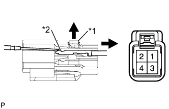
Text in Illustration *1 Stopper *2 Locking Lug Using a screwdriver, release the stopper.
-
Using a screwdriver, disengage the locking lug of terminals (3) and (4), and pull the terminals out from the rear of the connector.
-
-
REMOVE IGNITION SWITCH LOCK CYLINDER ASSEMBLY (for LHD without Smart Entry and Start System)
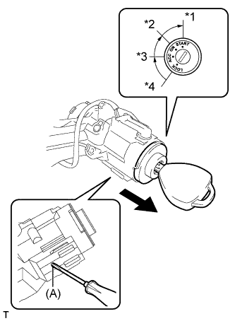
Text in Illustration *1 START *2 ON *3 ACC *4 LOCK
-
Turn the ignition switch to ACC.
-
Insert the tip of a screwdriver into the hole (A) in the steering column bracket assembly upper, and pull out the ignition switch lock cylinder from the steering column bracket assembly upper.
-
-
REMOVE IGNITION SWITCH LOCK CYLINDER ASSEMBLY (for RHD without Smart Entry and Start System)
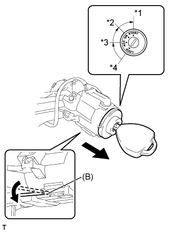
Text in Illustration *1 START *2 ON *3 ACC *4 LOCK
-
Turn the ignition switch to ACC.
-
Insert the tip of a small steel rod into the hole (B) in the steering column bracket and tilt it downward, as shown in the illustration, to disengage the ignition switch lock cylinder. Then pull out the ignition switch lock cylinder.
-
-
REMOVE UNLOCK WARNING SWITCH ASSEMBLY (except Manual Transaxle without Smart Entry and Start System)
-
Disengage the 2 claws and remove the unlock warning switch assembly from the steering column bracket assembly upper as shown in the illustration.
-
Disconnect the unlock warning switch connector from the steering column bracket assembly upper
-
-
REMOVE STEERING LOCK ACTUATOR ASSEMBLY (w/ Smart Entry and Start System)
-
Fix the steering post assembly in a vise between aluminum plates.
Note
Do not overtighten the vise.
-
Using a drill, drill a hole in the steering lock set bolt, to insert a screw extractor.
-
Using the screw extractor, remove the steering lock set bolt and remove the steering lock actuator and steering column clamp upper.
-